 Engineer News Network The ultimate online news and information resource for today’s engineer
To ensure precision motion control of OEM applications ranging from robotic joints to centrifuges, motor selection is crucial. With a typical choice including servo or stepper motors, specific brushless DC designs can also optimise design integration. Technology selection depends on an understanding of parameters ranging from speed of kinematic response to inertia, as well as mechanical design integration. Gerard Bush discusses the principles of motor selection for precision motion applications
When selecting a motor for a machine design, even one that demands precision control, the initial considerations are based on speed and torque characteristics. For applications such as robotic joint control, kinematic accuracy that relates to position and control velocity is also fundamental. Providing that the speed and torque requirements have been calculated, these criteria, along with inertial acceleration, can be selected through the motor manufacturers’ specifications.
However, in many cases, precise system power and accuracy requirements cannot be calculated until a prototype mechanical assembly has been tested. Meanwhile, initial motor selection can rely on the tribal knowledge of motors used in legacy machines of equivalent functionality, or motors can be oversized during prototyping, then downsized later when precise requirements are known.
Speed control
The step motor is often the first consideration when specifying a motor for precision control because of its strong cost position. However, its suitability depends on speed requirements, as the maximum speed of a step motor is limited due to its higher pole count. This can be an advantage compared to servos though, if high torque density is required. While a stepper can provide positioning sufficient for many applications, accuracy depends on system loading as a proportion of the step motor’s torque rating. At 10% loading, positional error is approximately ¼ of a whole step, or 0.5°.
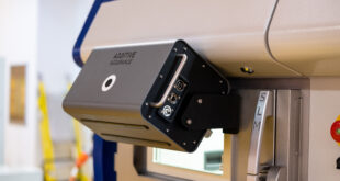
Alternatively, a servo motor offers much faster maximum speed. High-speed applications, including those above 5,000 RPM, are typically rotating a balanced inertia without any external loading, such as a centrifuge. As the system accelerates, radial bearing forces are the dominant bearing load, and their impact is proportional to system eccentricity. Generating a model of the radial bearing forces to determine the scope of torque requirements is typically a feature of prototype testing.
Instead, if a servo motor is accelerating and decelerating with an unbalanced inertia, for example, when controlling a joint in an articulating robot arm, inertial properties dominate the motor torque demand. Torque requirements for prototyping can be estimated from a model with inertial and kinematic properties of the robot/load system.
Positional control
In terms of control accuracy, the servo motor with position feedback is the optimum choice. In most cases, a servo can settle within ±10 encoder counts, but this also requires an encoder with sufficient positional resolution. The servo motor’s response is also critical; theoretically, the kinematic response of the motor should be linear with torque, but static friction makes a linear response impossible when starting and stopping a move. Therefore, high-accuracy systems need additional, specialised mechanics, designed to limit this effect.
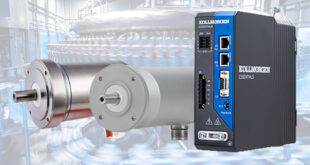
Brushless DC motors (BLDC) can also be used for positional control in combination with a feedback device. An additional encoder adds its own footprint and cost, but a BLDC motor is more efficient than a servo and offers higher torque density. They can also enable a simpler, more flexible integration approach that can aid machine design. Frameless BLDC motors can have a hollow shaft, allowing components to be placed through their centre, and their design also saves footprint and weight. These motors are often direct drive, connecting to the load without the need for transmission, which provides high dynamic and high-speed operation.
Inertia matching
Whatever motor technology is selected, matching the inertia of the motor and its load is crucial to optimise response time, and prevent operational challenges such as vibration. It’s possible to operate a large inertia ratio with the advantages of a smaller motor, yet still meet torque/speed requirements. However, this increases demand on power input, and careful selection is essential to avoid mechanical instability that can cause motor oscillation at higher frequencies.
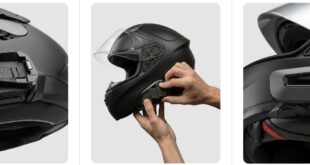
Ultimately, motor specification optimisation requires a thorough understanding of the application’s attributes. INMOCO’s engineers can help OEMs specify the most appropriate solution for requirements. As well as providing an array of motor types, INMOCO’s application specialists work alongside engineers from Performance Motion Devices. PMD develops precision motion control technology for robotics and machine integration. Together, this expertise can help OEMs achieve the most appropriate motion solution to fulfil the end users’ needs.
Gerard Bush is with INMOCO.