 Engineer News Network The ultimate online news and information resource for today’s engineer
When selecting a non-contact eddy current displacement sensor, a number of factors need to be considered, including temperature of the target, calibration, target thickness and size, speed of measurements and mounting, says Chris Jones
Although most engineers are familiar with non-contact eddy current displacement sensors, this article acts as a useful checklist of the factors that should be considered before specifying a sensor, as well as the benefits and limitations of this measuring principle.
Measuring principle
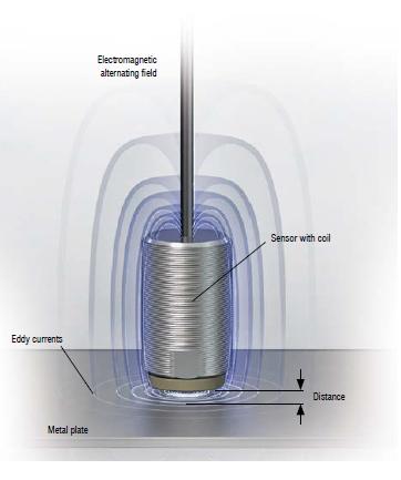
The eddy current measuring principle occupies a unique position among inductive measuring methods.
The principle is based on the extraction of energy from an oscillating circuit. This energy is required for the induction of eddy currents in electrically conductive materials.
A coil is supplied with an alternating current, causing a magnetic field to form around the coil.
If an electrically conducting object is placed in this magnetic field, eddy currents are induced, which form a field according to Faraday‘s induction law. This field acts against the field of the coil, which also causes a change in the impedance of the coil. This impedance can be calculated by a controller, which looks at the change in the amplitude and phase position of the sensor coil.
Advantages
There are several distinct advantages of using eddy current measurement sensors.
First, measurements are made on a non-contact basis and so are wear-free.
Second, the principle offers high precision, high resolution and high temperature stability.
The sensors can also be used on both ferromagnetic and non-ferromagnetic materials. The sensors also perform at high speed if required, with some sensor suppliers offering measurement speeds up to 100kHz.
With high measurement accuracies and frequency response times, together with an extremely robust design, eddy current sensors enable measurements to be made in tasks where conventional sensors have reached their performance limits.
Harsh environments
Eddy current sensors also perform well in demanding, harsh industrial environments where oil, dirt, dust, high pressures and high temperatures are present.
Some suppliers, for example, offer robust eddy current sensors with increased protection (to IP67) for harsh environments and pressure-resistant versions that withstand pressures up to 2,000 bar.
Custom capabilities
It is also important to look for a supplier that offers a wide range of different eddy current sensor designs, which will enable the optimal sensor to be selected for a particular application.
Applications for eddy current displacement sensors are often found where the standard versions of the sensors and the controller are performing at their limits.
For these special tasks, consider sensor suppliers that can modify the sensor according to your specific individual requirements. Typical modifications requested include modified sensor designs, miniature sensors (2mm to 4mm in diameter), target calibration, mounting options, cable lengths, modified measuring ranges and sensors with integrated controller.
Temperature fluctuations
Depending on the supplier, eddy current sensors can operate in ambient temperatures from -40°C to +200°C. However, temperature fluctuations occur during operation.
As the temperature of the target material changes, its resistance changes and so the accuracy of the sensor depends on the target temperature. It is therefore important to monitor the temperature of the target and compensate for this.
Micro-Epsilon, for example, provides an ‘Active Temperature Compensation’ feature on its eddy current sensors. This actively measures the temperature of the sensor, electronics, cable and controller, adjusting the measurement values accordingly.Calibration
To improve sensor performance, most eddy current sensors are factory-calibrated by the supplier to a specific target material. Some suppliers, however, offer advanced eddy current measurement systems that are able to calibrate themselves.
The eddyNCDT 3300 series from Micro-Epsilon, for example, can store up to four different material types.
Mounting and installation
Eddy current sensors are grouped into shielded and unshielded sensors. With shielded sensors, the field lines run closer together due to a separate casing. These are less sensitive to radial flanking metals.
With unshielded sensors, the field lines emerge at the side of the sensor normally causing an extended measuring range. Correct installation is crucial for good signal quality.
Target size and geometry
The relative size of the measuring object to the sensor affects the linearity deviation for eddy current sensors.
Ideally, the measuring object size for shielded sensors should be at least 1.5 times the diameter of the sensor and at least three times the coil diameter of the sensor for unshielded versions. From this size, almost all lines of the magnetic field run from the sensor to the target. Therefore, almost all magnetic field lines penetrate the target via the face and so contribute to eddy current generation, where only a small linearity deviation occurs.
Eddy current sensors have a relatively large spot size compared to their measuring range. For example, a 3mm measuring range will typically require a target size of 1.5 times this measuring range, i.e. 8-9mm.
However, this depends on whether the sensor is shielded or unshielded. If shielded, the measuring range of the sensor decreases. If unshielded, the sensor will offer a larger measuring range.
Target geometry is also an important factor. Eddy current sensors are often used to measure against rotating or curved shafts, where they measure oil gaps or vibrations.
However, almost all suppliers calibrate their sensors against a flat target. If this is the case, users must therefore perform their own linearity adjustments against the target geometry.
Most mid-to high-end eddy current sensor suppliers will compensate for curved targets, but it is important to check the supplier’s datasheet or ask for advice and guidance on sensor selection directly from the supplier.
Tilt angle and measuring signal
Many non-contact eddy current displacement measuring systems offer excellent linearity and high resolution, but only if they are installed at right angles to the target.
As exact right angle mounting of the sensor to the target is often difficult to achieve, the extent of deviation is different from one sensor supplier to another.
If the controller is not linearised for tilt angles, the measured values will deviate marginally from values measured in the right angle position. Hence it is important to know the influence on the measuring signal if the sensor is tilted.
Generally, a tilt angle of more than 6 degrees is possible with unshielded sensors than with shielded, but should be avoided. In principle, only a special linearised sensor will provide a precise signal.
A permanent tilt angle can already be logged in the controller with 3-point linearisation. This avoids any influence of this tilt angle on the signal quality.
Required target thickness
The principle of eddy current displacement measurement requires a minimum thickness for stable measurement results. This minimum thickness depends on the target material used and the measurement frequency used.
Shorter range sensors tend to use high excitation frequencies, which penetrate less into the target material, resulting in a requirement for a thinner target.
For example, the minimum target thickness of an aluminium target is 80 to 100 microns with displacements of 1mm or less. For steel targets, this increases to 400-plus microns.
Temperature fluctuations must also be considered here, as the thickness of the target material will increase as temperature increases. For example, if you are measuring a target where the temperature fluctuates by ±25°C, it is recommended that the minimum target thickness be increased by a factor of three.
Skin or penetration depth
Electromagnetic fields are attenuated on entering an electrically or magnetically conducting material.
The reduction in the field strength and therefore the current density is accompanied by losses that occur in the vicinity of the material surface.
The characteristic length at which the current density reduces to the value 1/e or to 37% is known as the skin depth.
Chris Jones is with Micro-Epsilon.