 Engineer News Network The ultimate online news and information resource for today’s engineer
Pipe leaks within concrete, ie, ‘slab leaks’ are identifiable with a thermal imaging camera, but due to a variety of influential factors, they aren’t always identifiable unless you know what to look for and have the right tools
Many homes today in various parts of the country are built with concrete and in-floor radiant heating in concrete slabs, and homes dating back to the 1950s as well.
As the odds are in favour of encountering concrete more than once, FLIR can help ease the process when it comes to inspecting this dense material. In addition to water leaks, radiant coil heating issues in concrete slabs are often of concern as well, so we’ll touch on that process as it pertains to conducting a thermal inspection on a concrete home.
Check out the tips and tricks below to learn more:
First, do you have the right tools?
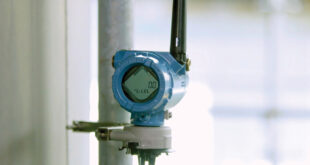
To find slab leaks in concrete (or detect malfunctioning radiant heating systems), you’ll want to invest in a thermal imaging camera with a high resolution and thermal sensitivity, as well as with the ability to adjust your level and span.
For concrete inspection, we recommend using a FLIR E8 camera and, at the higher end, one of the FLIR T-Series cameras.
Many use pinless moisture meters as a common way to detect moisture or verify the presence of moisture after a thermal inspection, but as pinless are only accurate up to one inch below a surface and concrete is near impossible to penetrate with a pin moisture meter, thermal is most ideal in these environments, almost always exclusively, to visualise the full scope of the problem.
With most of our thermal cameras aimed at this application, you’ll have the added benefit of FLIR Multi-Spectral Dynamic Imaging Technology (MSX), which is a combined picture overlay of both the thermal and visible image for enhanced image detail and enabling the ability to visualise previously marked areas of concern.
As no situation is the same, and you should always prepare for the unexpected, hygrometers, measuring tapes and a digital camera can also be utilized to best advantage alongside your thermal camera for jobs like this.
Once you have the right tools, you’ll want to keep the below factors in mind:
Temperature
Infrared cameras don’t ‘see’ water, but rather can visualise the impact water has on the temperature of surfaces around them due to the evaporation process.
With concrete slab leaks, contrast in temperature is important in enabling the thermal camera to visualise the source of a potential leak.
Typically, you aren’t running hot water in these old pipes below concrete, but rather ground water and well water and thus the contrast is dependent upon the severity of the leak as well as depth below the surface.
When it comes to radiant heating inspection in concrete, there’s more room for tips and tricks.
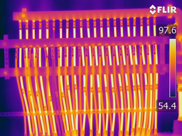
This image is of a manifold, and you’ll always want to start at the manifold as you can measure the temperature at the PEX supply and return, the difference is called the temperature rise, and most manufacturers will have a temperature rise (110˚F-135˚F as an example) of what the difference should be between supply and return.
If there is a major leak with the radiant heating, the supply will always be significantly cooler as the leaking water is not making it back to the boiler. This difference in temperature will show up much more sharply in a thermal image.
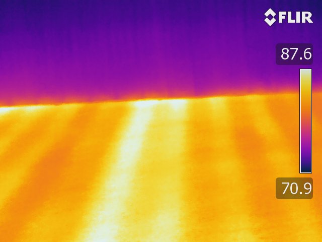
Delta T
The greater the change in temperature (Delta T), the greater the heat transfer. A trick we recommend is turning on the air conditioning if available (cold air is more dense and falls) to cool the slab, then turn on the radiant heater for 30 minutes and this combination tends to produce quality contrast images.
You can see this method was probably applied in the below image:
Angle
When conducting a thermal inspection with concrete, angle to the floor is very important. If you have too great an angle, all you’ll see is reflection. T
he recommended angle for thermal image capture, if you have too great an angle to the concrete floor initially, is 60 – 90˚, and many use a ladder to achieve this on site.
Infrared technology is not a substitute for visual examination, but it does provide vital clues that visual examination cannot offer. It detects infrared radiation (energy) levels being emitted from an object’s surface, and differences in radiation levels as well as the patterns (infrared signatures) they leave often indicate what is going on inside the structure.
When used correctly, thermal imaging inspection saves time and money, avoids unnecessary destructive damage and authenticates accuracy and successful job completion to your customer – a priceless benefit when working with concrete.