 Engineer News Network The ultimate online news and information resource for today’s engineer
Eliminating power transients when switching large motors or transformers during power outages or engine testing. John Stark reports
When large inductive loads – loads consisting of large motors and/or transformers – are transferred between two live power sources, eg, a normal source (1) and an emergency source (2), which may not be in synchronism, efforts should be made to eliminate line current transients that occur during this type of switching.
This situation exists either when retransferring from the emergency source to the restored normal source after a power outage, or transferring in either direction while testing the emergency power system.
Through the proper selection of transfer switches, emergency/back-up power system designers can dramatically reduce and effectively mitigate these transients and the problems associated with them.
Among the available options for switching large inductive loads, the dual-operator transfer switch is believed by most industry experts to be the most reliable.
For many, it is the best option for eliminating any excessive line currents that could exceed the instantaneous trip settings of protective devices in the system.
Effects of out-of-synch transfers
When a running motor is disconnected from its power source, the residual voltage produced by the motor’s generator action will decay in amplitude and frequency as the motor slows down. This may take a considerable length of time, depending on the type of motor and the nature of the connected load.
So, even if two power sources are in synchronism when a transfer is initiated, induced voltage transients can still cause high currents at the moment such motor loads are actually transferred.
Similarly, when a transformer is disconnected from its power source, a certain amount of time is required for the magnetic field to collapse.
The release of energy stored in the transformer’s windings and core can generate high currents at the time of transfer – even if the two power sources were in synchronism when transfer was initiated. These current surges are the result of an out-of-phase transfer between two sources and can exceed the instantaneous trip settings of protective devices in the system, resulting in tripped circuit breakers.
This lack of synchronisation is analogous to two musical instruments that are out of tune and not playing together in harmony.
The consequence of music with sound waves not in harmony is a terrible sound and a headache; the consequence of asynchronous electrical sine waves not in balance is an out-of-phase transfer situation.
In this instance protective feeder breakers would have a high possibly of tripping. This potentially could cause a branch circuit or even an entire system to go down.
Compensating for out-of-synch transfers
Three methods commonly utilised to prevent such transients from occurring include: 1) A time delay operator interlock system; 2) A synchronising check function, aka, in-phase monitor; and 3) A dual-operator transfer switch with adjustable center off delay feature.
Following are explanations of how each method mitigates these power transients, as well as the pros and cons associated with their use.
Time delay operator interlock function
A time delay operator interlock function can be programmed into the transfer switch’s controller and powered by the transfer switch’s control circuit. This function disconnects large motors and/or transformers just prior to transfer and automatically reconnects them after an adjustable time delay, during which they will have had time to de-energise.
With this arrangement, normal inrush current is experienced upon reconnection to the live power source.
Advantages:
- Can be inexpensively added to a transfer switch
- Time delay can be easily adjusted to suit load requirements
- Flexibility to select disconnect prior to transfer or after transfer
Disadvantages:
- Requires external wiring from the transfer switch to the motor or transformer disconnect device. This method typically requires multiple circuits — one for each motor or transformer controlled — and is difficult to implement in older installations.
Synchronising check function/in-phase monitor
A synchronising check function inhibits load transfer, ie the transfer switch from transferring, until the two live power sources are in synchronism. This function can be adjusted to permit the transfer switch to operate only when the replacement power source is typically and electrically within approximately 10 degrees of the connected power source.
Depending on the differences in frequency and phase angle between the two power sources and the contact-to-contact transition time, the transfer is made at or very near synchronism. This function can be used to control unidirectional transfers (emergency to normal) or bidirectional transfers.
Advantages:
- When the load does not include heavy transformers and the system is adjusted properly, the transfer of motor loads can be accomplished without any appreciable power dip due to the slight delay in transferring two available sources of power.
Disadvantages:
- The synchronising check function is an inherently passive one, fully dependent upon the selection and adjustment of the emergency power generator’s governor.
- The exact time of transfer initiation cannot be controlled. If the frequency of the target source is more than two cycles out of sync, or if the connected power source is unstable, the transfer switch will not transfer until the target source frequency is in synchronism. If the switch is unable to retransfer to the utility source, it will remain connected to the emergency source until that source is lost (eg, the engine generator runs out of fuel).
- The synchronising check function has no control over the rate of decay experienced from the time a motor load is de-energised until the transfer switch closes to the target power source. Depending on the switch’s contact-to-contact transition time, a heavily loaded motor could go out of synch in the time needed for the transfer. This problem could be magnified in larger transfer switches which have longer contact-to-contact transition times.
- The synchronising check function does nothing to prevent the power transients that occur when transformers are switched at high speed. Because the sinusoidal line voltage wave form deteriorates once the transformer is disconnected, the magnitude of these power transients is determined by the length of time required for the transformer voltage to decay. This, in turn, is dependent upon the type of load served by the transformer. A synchronising check function, therefore, does nothing to eliminate the transients that occur when switching transformers at high-speed.
- The synchronising check function is totally ineffective during manual transfer under load.
- The synchronising check function is also totally ineffective when transferring between a failing power source and a live one (single phase or brown-out condition). If the transfer switch logic senses a partial failure of a source, the synchronising check function must be bypassed to allow transfer. In such a case, an out-of-phase transfer cannot be avoided and could very well trip the circuit breaker that feeds the only good power source. If this happens, all power to the critical load could be lost.
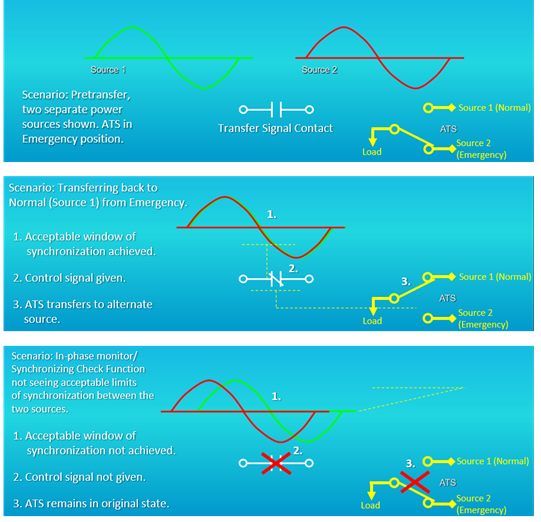
- The in-phase monitor introduces a variety of sensitive and adjustable electronics and circuitry into the system, which can fail over time. Figure 1 shows how the in-phase monitor solution works and illustrates the phase relationships in the 3-phase power source. In this example, there is no power outage – both the utility (normal source 1) and the generator (emergency source 2) are available and the user is switching between the two available sources to conduct a test. With the sync-check feature, the voltage values from both sources are measured and reported, and the controller monitors this phase relationship. (The example is simplified. It shows only one red and green sine wave; in reality, there would be three sine waves for three phase power of each source.)
In the graphic the (white coloured) contact is shown in the sync check function. It will close when it is satisfied (in-phase) and allow the (yellow coloured) automatic transfer switch (ATS) to transfer power.
The middle graphic shows the successful operation of the transfer. In the bottom graphic, the switch will not transfer because the sync-check function within the in-phase monitor did not see an acceptable window of voltage and frequency between the two available sources.
There are several real-world situations where a sync-check function could be a problem.
Say, for example, that you are feeding an equipment load in a remote location. The equipment load loses utility and is running on a generator.
Then, utility (source 1) comes back and load is still being fed by the generator (source 2). The transfer switch will sense that utility is back, but if synchronisation between sources is never achieved, (as previously mentioned) the ATS will stay on generator power and the generator could potentially run out of fuel.
At remote sites or in areas of bad weather, operators may not even know the generator is running and the ATS was never transferred back to utility (until the generator runs out of fuel).
Dual-operator transfer switch
The dual-operator transfer switch design eliminates high current surges by intentionally delaying the completion of the load transfer, thereby disconnecting the loads and allowing them to de-energise before reconnecting them to an alternate power source. This is accomplished by introducing a time delay between the opening of the closed power contacts and the closing of the open power contacts.
Preset at the factory, the default delay is the length of time it takes to complete a normal transfer with a dual-operator switch and is typically sufficient to eliminate current surges. This delay period can, however, be adjusted to whatever length of time is necessary to achieve the desired results.
Advantages:
- Foolproof operation under all transfer conditions, including manual operation.
- Positive transfer without reliance on sensitive monitors. There is no need to worry about finding an acceptable window of synchronisation – you will get a transfer and you can control when the transfer occurs.
- Successful operation is totally independent of the frequency of the two power sources.
- Because a dual-operator transfer switch is an active device, the exact time of transfer initiation will be known and it can be controlled.
- Requires no wiring or coordination between the transfer switch and electrical equipment or between normal and emergency power sources.
- Flexibility of control schemes. For instance, when utilised in conjunction with a multiple-engine, generator control switchboard, the dual-operator design accommodates load shedding. By switching the main contacts to a centre-off position – for a programmable period – a dual-operator switch eliminates the need for separate load shedding devices.
Disadvantages:
- A slightly longer transition time for transfer.
- Can be slightly more expensive than the in-phase monitor with synchronising check function with some manufacturers, but not all.
More on the dual-operator transfer switch
The dual-operator transfer switch design eliminates high current surges by delaying the completion of the load transfer, which allows disconnected electrical loads to de-energise before reconnecting them to an alternate power source.
Because a dual-operator transfer switch is an active device, users can control the exact time a transfer is initiated.
For example, Russelectric dual operator transfer switches are preset at the factory for 3 seconds, but the delay period is programmable up to 999 seconds.
The default window is usually sufficient for regenerative power to decay. This is especially true for large inductive motors under heavy physical loads, which slow down quickly.
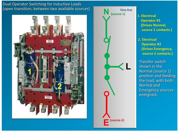
Figure 2 shows an example of dual operator switching for inductive loads, with open transition between two available sources. (Next to the photo is a one-line graphic, with an N for normal source 1, L for load, and E for emergency source 2.)
When the switch is ready to transfer, the first motor to operate gets a signal from the microprocessor controller.
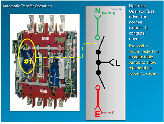
Operator #1 drives the normal source contacts open. In Figure 3, the load source is disconnected (represented in black) for the adjustment period to allow the regenerative voltage to decay.
Again, the set time window is typically 3 seconds, which is usually enough time to allow the degenerative power to decay.
The load source is disconnected for the adjustment period. The set time window is generally, again, three seconds, which is usually enough time to allow the degenerative power to decay.
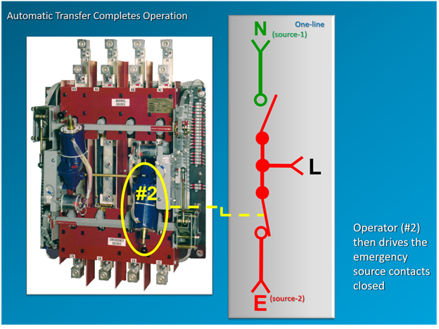
Once the three second delay elapses, with load disconnected, Operator #2 then drives the emergency source contacts closed and the load will be fed by the emergency source. This is shown in Figure 4.
Dual operator switch has additional load shedding capabilities
The dual operator has an important extra benefit: it can be used for load shedding when non-essential loads must be dropped following loss of generator capacity. The ATS can be set in three positions: emergency (generator), off, and normal (utility).
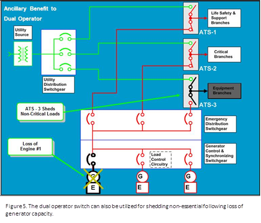
Figure 5 shows a scenario in which one of three engines goes off-line and the remaining generator capacity cannot feed the entire building. In this case, the operator chose to dump equipment branches (loads deemed non-essential, such as chillers and non-emergency lighting).
The dual operator switch can be programmed to hold the ATS in the centre-off position indefinitely.
By contrast, a sync-check relay with a single operator can only switch to normal or emergency positions. Users can still dump equipment branches, but only to a black utility source, and if the utility feed suddenly returns, the equipment branches would lurch to life. This could have unintended negative consequences, and as a result, most users want more control over their system.
Conclusion: Dual-operator transfer switch by far the most reliable option
The dual-operator transfer switch is by far the most reliable method of switching large inductive loads because it is flexible, simple, and foolproof.
With this type of switching, excessive line currents that can lead to short circuits are eliminated. Through the proper selection of transfer switches, emergency/backup power system designers can dramatically reduce and effectively mitigate transient currents and all the problems that go along with them.
John Stark is, Marketing Communications Supervisor, Russelectric Inc.