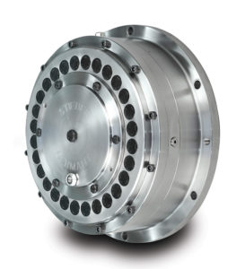
Dr Torsten Kretschmer explains what is involved in the design of backstops and cites important aspects in connection with safety regulations to be expected in the future
Overrunning clutches and backstops play a fundamental role in heavy industry such as mining and iron and steel, but also in food processing and all applications in which goods and materials are moved by conveying equipment.
Their principal task is to prevent reverse running and uncontrolled acceleration of the system in the event of a drive failure (eg, loss of supply voltage). It is important, therefore, that these components are specified and designed with a high degree of precision.
Backstops are a fundamental safety component for preventing an uncontrolled change of direction and speed under the influence of gravity. A fully loaded, blocked belt conveyor system can impose huge torques on the drive.
However, with the right know-how and an in-depth knowledge of the prevailing conditions of use, it is possible to design the backstop in a compact and cost-efficient manner and still safeguard the drive train reliably against overload. Backstops also merit closer attention from the point of view of technical aspects of occupational safety and health and accident prevention.
Design principles
To design the backstop correctly, the plant designer requires exact data regarding the torques present on the conveyor line. In cases of doubt, many customers and designers work with a larger safety factor, although it is naturally desirable to avoid over-dimensioning and unnecessary costs.

Plant operators should therefore give the job of determining the torques occurring to experienced design engineers, who are able to calculate these very accurately. This information helps the overrunning clutch manufacturer in turn, working in tandem with the customer, to coordinate the performance data of the backstop precisely to the torques to be expected.
In the ideal case, the backstop is designed in parallel with the drive unit, because the motor and gearbox play a key role for its dimensioning and performance parameters.
Backstops can either be flanged directly onto the transmission housing on the fast-running transmission shaft or mounted externally on the shaft end of the slow-running transmission shaft.
For reasons of greater ease of servicing – the transmission can be dismantled without having to strip down the belt – some users prefer to have a transmission mounted separately from the conveyor line. In this case an external backstop between the conveyor line and the transmission is the best solution.
The component must have a suitably high torque capacity here, which is reflected in the construction size and possibly the procurement costs. If the aforesaid advantages for maintenance can be sacrificed, a transmission-mounted design of backstop is commonly recommended.
Since the torque loading is lower here than with external mounting, it can normally be of smaller dimensions and be purchased at a lower price.
Load balancing and torque limiting
The number and configuration of backstops are dependent, for the most part, on the application. On conveyors with multiple drives and a corresponding number of backstops without torque limiting, it should be assumed that only low load balancing takes place. The reason for this is the delayed engagement of the various backstops (RS) in consequence of tolerances in the stops, different belt elongations at the stops, different friction states (efficiency rates) in the belts etc.
Figure 1 clarifies this scenario. It is shown that RS1 has to transmit considerably more torque than RS2 – in an extreme case, even the entire reverse torque. In practice, safety factors of up to 3 times the drive torque result from this. Load balancing between RS1 and RS2 does not take place in this situation. The point of RS2 can then only be a safety backup, which at the same time means, however, that RS2 must be designed with the same safety factor as RS1. It isn’t hard to see that both RSs turn out to be disproportionately large in this way.
Figure 1: Torque increase in a multiple-drive plant
Torque(кНм)
Windup(°)
BS1
BS2
Application torque
Rated torque BS1
Figure 2 shows the measurement results for the torque at two standard backstops without torque limiting, which are installed on a shaft. The results show that a 20% higher torque is present at one of the two backstops – with corresponding consequences for the design.
Figure 2: Torque at two backstops without torque limiting
Torque in Holdbacks Duing Loaded E-stop
Torque (ft-lbs)
Time(sec)
North Holdback
South Holdback
The load balancing can be improved by means of torque-limiting backstops, so that the backstops can be designed smaller without reducing safety. Two design configurations on real examples for the slow-running shaft and the fast-running shaft can be demonstrated below for this:
Design for the slow-running shaft
Application: Overland belt conveyor with backstops without torque limiting on the slow-running shaft
Drive output 3200kW
Safety factor (customer specification) 1.5
Speed of drive roller, belt 55rpm
Return torque of the loaded belt 53kNm
Customer specification: The backstop must overcome the torque loading following an aborted start.
Torque capacity of the backstop ≥ (3200 kW × 1,5 × 9550) / (55/min) = 833,5 kNm
The calculation for backstops with torque limiting on the slow-running shaft is completely different. In this case, the backstop is adjusted so that it can safely transmit the return torque of the loaded belt (safety factor: 1.3).
Slipping torque of the backstop ≥53 kNm ×1,3 =68.9 kNm
In the case of an aborted start, the backstop slips until the tension in the belt is relieved.
Design for the fast-running shaft
Application: Inclined conveyor with backstops without torque limiting on the fast-running shaft
Drive output 950kW
Safety factor (customer specification) 1.5
Speed of fast-running shaft 500rpm
Return torque on the fast-running shaft 15kNm
Torque capacity of the backstop ≥ (950 kW ×1,5 ×9550) / (500/min) = 27.2kNm
In the present case the customer selected a standard backstop with a maximum torque capacity of 72 kNm, which was damaged during an aborted start with an overloaded belt. In this case even a higher safety factor or the installation of an even bigger backstop would not be a remedy, purely because the transmission is not designed for this and a backstop with suitable torque capacity no longer fits onto the transmission from the size point of view.
By contrast, a torque-limiting backstop with suitably adjusted slipping torque and a high speed capacity in slipping mode is expedient.
Backstops with torque limiting on the fast-running shaft: the backstop is adjusted so that it can safely transmit the return torque of the loaded belt (safety factor: 1.3).
Slipping torque of the backstop ≥ 15 kNm ×1,3 = 19.59 kNm
In the case of an aborted start, the backstop slips until the tension in the belt has been relieved.
As can be gathered from the design examples, torque-limiting backstops, which can safely hold the restoring torque (safety factor 1.3), can be specified that are much smaller than a conventional backstop without sustaining damage in the event of an aborted start. Stieber recommends a safety factor of 1.3 on the restoring torque, if permissible.
Safe design of load-balancing backstops
As well as the restoring torque, the design depends substantially on the efficiency factor in the conveyor system and the dynamic slipping torque of the stop that is set.
Example 1 (See Image 5)
Starting out from the assumption that
RS1 takes up 65% of the full load drive torque (VL) and RS2 35% of the VL
the breakaway torque is set at 60% VL respectively
the dynamic slipping torque is smaller than the static (µdyn = 0.8 µstat)
The following situation results:
SEE DIAGRAM 1
Full load drive torque (VL)
RS1 slips at 48% VL
Energy dissipation in RS1 due to slipping
RS2 at 52% VL – x -> no slipping
Belt system at 100% VL – x
The efficiency in the belt system (x) basically has a positive effect, ie, regardless of its specific value the overall belt will not slip.
The example makes it clear that the load balancing between two backstops on a common shaft can be optimised by means of torque limiters and the components can possibly be designed smaller. However, a condition for this is a careful calculation on the basis of exact application data, as is to be recognised from the second example:
Example 2 (See Image 6)
The basic assumptions correspond to example 1 with the sole difference that the breakaway torque is set respectively at 55% VL. Depending on x (efficiency in the belt system), two possible scenarios result:
SEE DIAGRAM 2
Full load drive torque(VL)
Backstop1 slips at 44% VL
Energy dissipation in Backstop1 due to slipping
Backstop2 at 56% VL – x
Belt system at 100% VL – x
Backstop1 slips at 44% VL
Energy dissipation due to load dropping
Belt system at 88% VL, 12% of load thrown off
As already mentioned, the efficiency in the belt system (x) has a positive effect on the design of the backstop. The more precisely the efficiency x and the operating conditions are known, the more precisely the backstop can be designed. It is also possible to implement a smaller construction size. If this value is not known, Stieber recommends a safety factor of 1.3 on the return torque of the loaded belt, unless otherwise specified.
Each application naturally makes its own special demands, and the calculations for the design of backstops should always be carefully checked by experts who have experience of these solutions. Presupposing the relevant technical expertise, it is possible to specify cost-effective yet safe and reliable solutions.
Controlled release
Electric motors are not normally designed to start up fully loaded conveyor belts. They would otherwise have to be extremely over-dimensioned and would be inefficient in normal operation. The next step following the response of a backstop is therefore the controlled release of the conveyor belt. How long this takes depends to a large extent on the type of backstop installed.
Ideally, a backstop that is to be released mechanically or hydraulically permits a controlled release of the belt. In systems with more than one backstop, simultaneous and gradual release by means of a central hydraulic system is particularly efficient and convenient. This allows the conveyor to be run in reverse in a controlled manner and quickly unloaded.
One practical example is the case of a coal conveyor in a loading port. If the belt, fitted with a conventional backstop, stops following an interruption in the power supply, it must be unloaded before the system can start up again. This might take an entire day and incur huge costs due to unscheduled docking times, among other things.
A backstop with a release function, on the other hand, makes it possible to release the conveyor in a few minutes, so that loading of the vessel can then proceed according to plan.
Hitherto most types of backstops only permitted reverse running, if at all, to a limited extent, and certainly not at high speed. However, Stieber now offers products that no longer have this drawback. Operators of conveyor systems can hereby reduce stoppage times due to unloading following a drive failure to a minimum.
While conventional backstops have plain bearings, type RDBK and RDBR backstops from Stieber have a patented roller bearing assembly. They are thus able to run in reverse for a long time and above all at high speeds.
Operational trials and statutory regulation
The testing of backstops in operation is not currently prescribed, in part due to the cost and production downtime associated with this. On the other hand, backstops have a key safety function and the application of a maintenance and testing programme guaranteeing the reliable functioning of these components in an emergency seems more than justified.
With its countless mining businesses, Australia is a pioneer when it comes to safety standards for large conveying systems. The Australian machinery safety standard for belt conveyors for bulk materials AS/NZS 4024.3611:2015 describes the requirements for equipment widely used in mining, for example. Section 2.2.3.2 goes into detail about redundant design and component failure:
“2.2.3.2 Mechanisms for safeguarding against uncontrolled acceleration
Conveyor systems that can accelerate in an uncontrolled manner due to the effect of gravity must be equipped with mechanism(s) that automatically prevent such acceleration. Where a belt, a chain drive, a fluid coupling or a similar component is connected between motor and driven shaft, a mechanism must be installed to safeguard against uncontrolled acceleration, in order to prevent ‘bolting’ if the interconnected component fails. On chain conveyors more than one such mechanism may be required.
If the failure of an acceleration safety device causes a risk to persons, uncontrolled acceleration must be prevented by two automatically responding mechanisms, wherein each of these mechanisms must be able to hold the entire load by themselves. These mechanisms must be monitored for wear and perfect operation. Each acceleration safety device must be designed so that it can stop and hold at least 150% of the maximum load of the conveyor system.
NOTE: Such mechanisms include brakes and backstops among other things.”
In view of the greater attention paid to occupational health and safety, it cannot be ruled out that safety regulations in certain fields or regions are updated to the effect that regular checks of safety mechanisms under operating conditions are required. For example, it could be the case that the operator must cause an emergency stop situation of a fully loaded conveyor to check that the backstops and comparable components are functioning properly.
Even if operators can be pleased with a positive test result, they may still face the problem after that of their blocked conveyor system having to be unloaded before production can be resumed. Anyone who has backstops that permit controlled reverse running in this situation can perhaps take care of the release process within a few minutes. In view of the cost of production downtimes, more and more operators are deciding in favour of such components.


Dr Torsten Kretschmer is Technical Director at Stieber GmbH.
 Engineer News Network The ultimate online news and information resource for today’s engineer


