 Engineer News Network The ultimate online news and information resource for today’s engineer
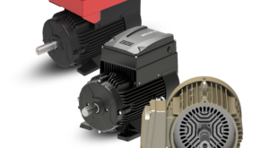
When specifying brushless DC motors, the designer will of course consider key parameters such as operating speed and torque, along with voltage and current. Just as important, but often overlooked, is the stall torque of the motor. Matthieu Bouat explains exactly what stall torque is, the physical parameters that affect it, and how you should factor it into your design considerations
Apply sufficient power to a brushless DC (BLDC) motor, and it turns. Remove the power, and it stops. But there is a condition in between where power is applied but the motor is not moving. This is a motor that is at stall. In this state, with power applied, it is very much a live motor; just because it is not turning does not mean current isn’t flowing through the windings.
Indeed, quite the opposite. At stall, an excess of current is flowing, heating up the motor coils; if stall conditions are maintained, or frequently repeated, these stresses can quickly add up to trouble.

Stall torque defined
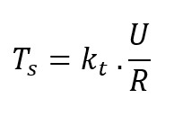
The stall torque of a brushless DC motor is dependent upon the torque constant, the stall current and the static friction torque. In most applications we can ignore the static friction torque, as it will be a negligible overall contributor to stall torque. In that case, we can state that the stall torque is given by: (see image 5 for equation)
Where Ts is the stall torque, kt is the torque constant, U is the voltage and R is the phase resistance.
The motor supplier will specify the stall torque for a given motor. There are physical parameters that will impact on that figure, but also there are factors that contribute to a tolerance in the stall torque which can be significant.
The torque constant itself has a typical tolerance of ±10%. Of this, approximately ±2.5% is caused by variation of the magnetic strength of the permanent magnet, i.e. variation of the magnetic remanence. The specific tolerance of this value depends on the manufacturing process capability of the supplier. The remaining ±7.5% of the torque constant tolerance is mainly due to phase setting.
The phase resistance of the motor (ohms) also affects the standard tolerance, and its contribution is usually given to be ±8%. It is due to the variation in the length of the wire while winding it. This is inherent to the manufacturing process.
What this all means is that, before we’ve even begun to consider external influences, we must allow for a tolerance of ±18% in the specified stall torque value.
Impact of temperature change
With the uncertainties of the manufacturing process understood, the designer must now consider the physical influences of the application, with temperature being perhaps the most important. Temperature can be an extrinsic factor (environmental temperature) or an intrinsic factor (joule losses of the coil), or both. That is the reason why phase resistance is always given for a certain temperature.
Increased temperature leads to increased phased resistance, in a linear relationship that equates to an increase of about 0.39% per °C. Temperature will also have an impact on the remanence of the magnet. With typical magnets used in brushless DC motors, assuming the temperature remains below the temperature of demagnetisation, the temperature increase will result in a drop of the torque constant of roughly 0.11% per °C.
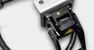
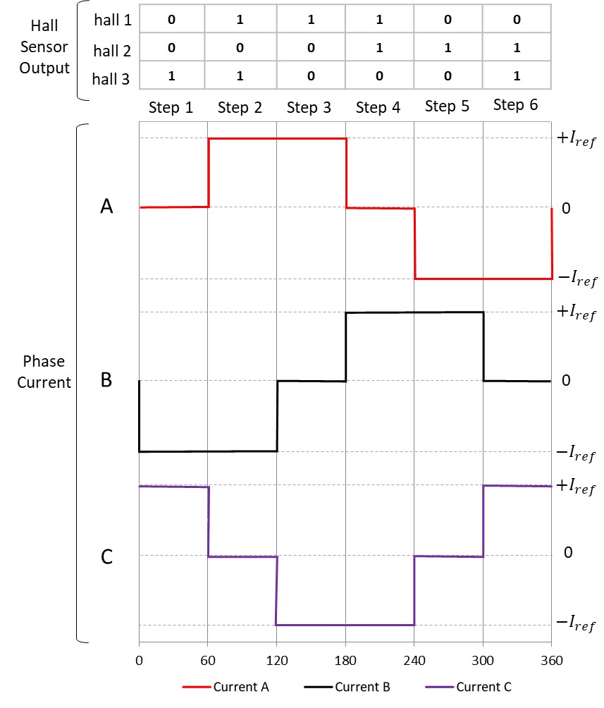
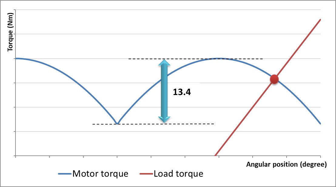
The designer must also consider the influence of the driving method – particularly when the application makes specific use of stall torque, as in our electric gripper example. In a conventional 6-step driver (using hall sensors), there is an associated ripple in the output torque of the motor. The difference to the top and the bottom of this ripple is equal to 13.4% of the maximum torque available. In this 6-step driver, the actual stall torque of the motor will be within this 13.4% tolerance range of the torque ripple.
Stall torque equation
An alternative method of driving the motor is field-orientated control. There is no torque ripple with this method of control – torque is constant no matter the rotor position, and there is no ripple to influence the stall torque value.
We can see, then, that there are many factors that impact the stall torque of a motor in a given application, and designers need to consider all of these influences. There may be a temptation simply to specify more powerful drive electronics, but this can have detrimental impacts in size, cost and power consumption.
Portescap has extensive expertise to help engineers understand all of the factors that influence stall torque and has tested its motors under real-world conditions. Portescap’s engineers are always on hand to help designers select the optimum motor/drive package to meet the requirements of the application, and to provide design and specification support along the way.
Matthieu Bouat is an Application Engineer at Portescap.