 Engineer News Network The ultimate online news and information resource for today’s engineer
Brushless DC motors are increasingly popular options for a host of critical applications where size, performance and reliability are important considerations. But designers of motion systems can face challenges when selecting or developing PWM electronics to drive these motors. Matthieu Bouat discusses the parameters that designers should consider when developing the electronic control aspect of the motion system, particularly where factors such as battery life and the overall size and weight of the package are key concerns
In any brushless DC motor-driven system, the role of the control electronics, the amplifier, is to vary the supply voltage or the current, or both, to achieve the desired motion output of the motor. There are a number of different options for the amplifier. A linear amplifier adapts the power delivered to the motor by linearly changing the voltage or current. It dissipates the power which is not delivered to the motor, resulting in the need for a large heat sink to dissipate the power, increasing the amplifier size and making it more difficult to integrate into the application.
In contrast, a chopper amplifier modulates the voltage (and current) by switching on and off the power transistors. The primary advantage is that it saves power when the transistor is off. This helps save on the battery life of the application, causes less heating and allows a smaller size of the electronics.
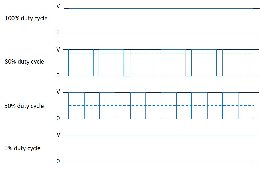
Most commonly, chopper amplifiers use a PWM (pulse width modulation) method, varying the duty cycle at a fixed frequency to adjust the voltage or current within the desired target value.
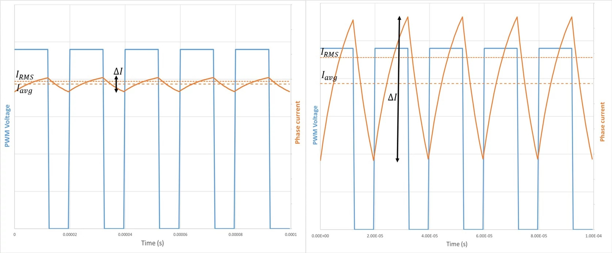
The switching frequency is a fixed parameter, making it easy for electronic designers to filter acoustic and electromagnetic noise generated. It is useful, however, to understand some other basic physical phenomena to avoid unexpected performance issues. Most notably, the switching on and off of the transistors leads to current rise and fall at each cycle, which can be problematic.
While the average current – established by the duty cycle of the switching electronics – defines the motor torque, the ripple current generates extra Joules losses (heat) and can have huge impact on the RMS (root mean square) current, without any corresponding increase in torque. Since there are no brushes the ripple current doesn’t compromise the lifetime of the brushless DC motor as it would in a brushed DC motor, but it wastes energy (potentially compromising battery life in portable applications) and may require a heat sink, adding size and weight to the application.
The ripple current also causes iron losses, forming circulation eddy currents that are proportional to the square of motor speed and to the square of motor current. Iron losses have a direct impact on motor power, and it is easy to see, being a squared relationship, how a high ripple current can quickly generate significant iron losses.
Reducing current ripple
It is important, therefore, to keep current ripple as low as possible, and there are a number of ways in which we can do this.
The first is to consider reducing or adapt the power supply voltage, given that current ripple is directly proportional to this voltage. A high voltage can be useful where the application requires high speed or high power, but if these extremes are not needed, then a lower supply voltage will be beneficial to reduce the current ripple.
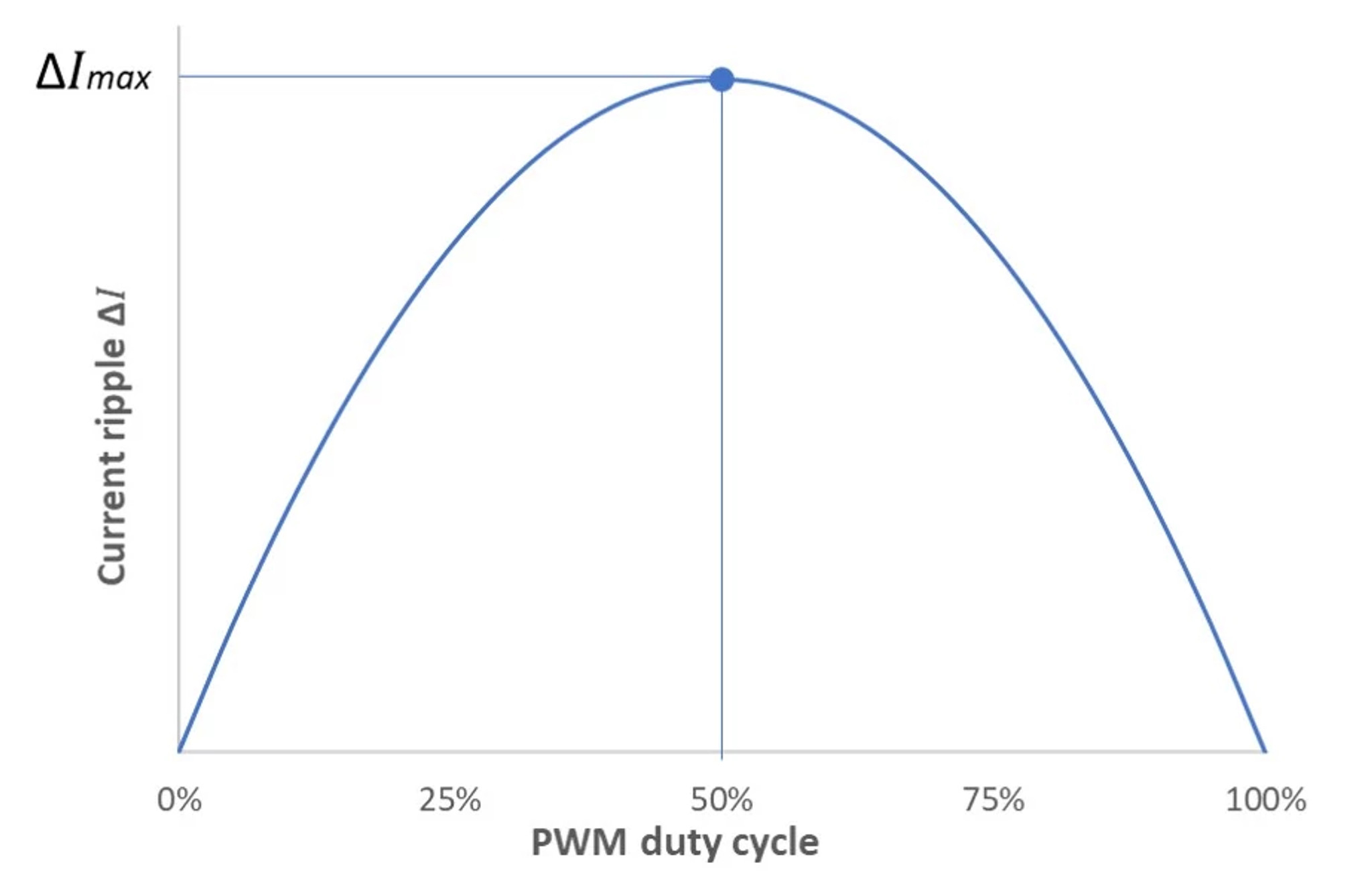
Further, operating under the same load point with a lower power supply voltage will also increase the duty cycle, which will reduce the current ripple even more. Generally, it is important to keep the duty cycle of the PWM as far as possible from 50%, which is the worst case.
A second option is to increase the PWM frequency. With a shorter cycle time, the current will have less time to rise, meaning less ripple. Portescap recommends using PWM frequencies not less than 50 kHz for brushless DC motors. PWM frequencies of 80 kHz or more would be even more appropriate for motors having very small electrical time constant.
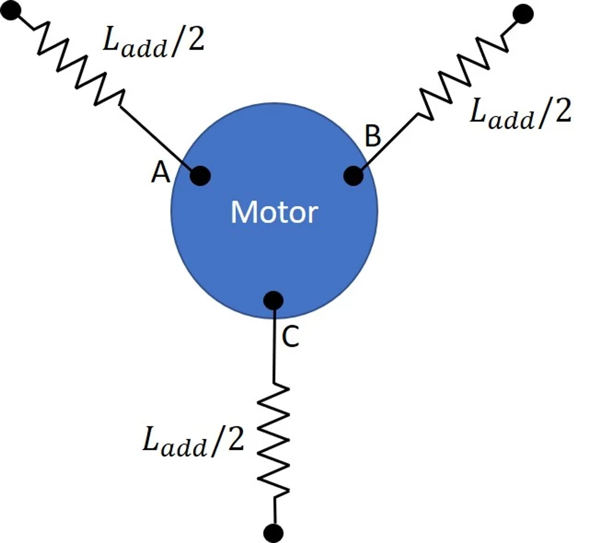
Finally, we can consider increasing the inductance, adding external inductance components to slow down the rise and fall of the current and hence reduce current ripple. However, while adding inductances of, for example, several tens of µH can work on paper, in practice there may not be the room to integrate these components, particularly in applications where space is limited. Therefore, it is usually wiser to explore the two other options first.
PWM has many advantages over other forms of control, and it is easy to see why it is the most widely used solution for driving brushless DC drivers. The affordability and availability of electronic components make it simple to set an adequate PWM voltage and to use a high PWM frequency, reducing ripple and avoiding the need to use additional inductances. This minimizes additional energy dissipated by Joules losses, helping to maximise battery life, while enabling designers to minimise the size and weight and the electronics, which is key for example in portable devices with embedded electronics.
As ever, it can pay dividends to engage with a knowledgeable supplier at the earliest stages of a design. Portescap engineers are on hand to help you define suitable electronics to work with brushless DC motors in even the most demanding applications.
Matthieu Bouat is an Application Engineer at Portescap.