 Engineer News Network The ultimate online news and information resource for today’s engineer
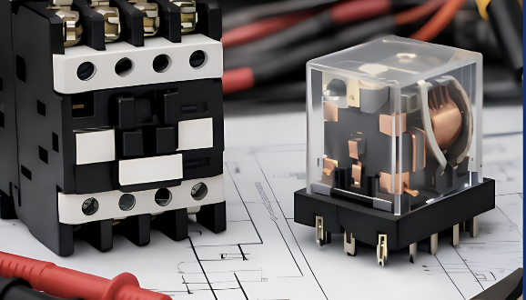
Chris Rhodes explains the key differences between contactors and relays, including their electrical characteristics, load capacities, switching mechanisms, and ideal industrial applications. He also outlines how engineers and facility operators can select the appropriate device based on factors such as current load, duty cycle, and system requirements
Is it a relay or a contactor? Getting the answer wrong can be the difference between a smooth running operation and a total system meltdown. While both act as the ‘gatekeepers’ of electrical current, they are engineered for very different workloads.
Today, we are stripping back the jargon to compare relays vs. contactors. From design architecture to industrial applications, here is everything you need to know to make an informed decision for your next project.
What is a contactor?
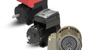
A contactor is an electromechanical device designed to manage the flow of power in high capacity electrical circuits. By utilising an electromagnetic coil to actuate internal contacts, it allows for the safe and efficient regulation of heavy electrical loads by either human operators or automated systems. These devices are essential in environments that demand the frequent cycling of high-current or high-voltage machinery.
How it operates
When an electrical signal reaches the contactor’s coil, it creates a magnetic field that pulls the contacts into place, closing the circuit and delivering power to the connected equipment. Once the coil loses power, the magnetic field collapses, and the contacts spring back to their default
state, cutting the current. This design enables the remote management of hardware without requiring the operator to manually interact with high-power lines.
Built for performance
Engineered to withstand rigorous electrical environments, contactors feature heavy-duty contacts, robust housing, and specialized arc-suppression components that shield the device from wear during operation. These durable traits make them the standard choice for controlling industrial motors, large compressors, HVAC heating elements, and other high-demand electrical systems.
Contactors are widely used in industrial and commercial environments, including:
● Motor control systems for pumps, conveyors, and compressors
● HVAC systems, including chillers and large air handling units
● Industrial automation and manufacturing equipment
● Power distribution panels and electrical control centres
● Lighting control systems in commercial and infrastructure facilities
By effectively managing heavy current loads and enduring high-frequency switching, contactors play a vital role in ensuring the safety and reliability of electrical systems within industrial automation and power control sectors.
What is a relay?
A relay is an electrically activated switch designed to manage low-to-mid-range power circuits via an independent control signal. By utilising electromagnetic or electronic actuation, it allows one circuit to trigger the opening or closing of another. This provides a safe, efficient method for governing electrical systems without requiring direct physical contact with the primary power flow.
How a relay operates
A standard electromechanical relay is composed of an internal coil, a set of movable contacts, and a protective casing. When a signal energises the coil, it produces a magnetic field that shifts the contacts. Depending on the relay’s specific design, this movement either bridges the circuit to allow flow or breaks it to stop flow. Once the control signal is removed, the contacts spring back to their default ‘resting’ position.
Precision and isolation
Relays are primarily deployed in scenarios requiring exacting control, signal routing, or electrical isolation. They act as a critical bridge, allowing low-power devices, such as PLCs or microcontrollers, to safely toggle higher-voltage equipment. This setup ensures that sensitive control electronics remain shielded from the potential interference or damage of the main electrical load.
Relays are widely used in applications such as:
● PLC control panels and industrial automation systems
● Signal switching and control-logic circuits
● Protection and monitoring systems
● Communication and interface circuits
● Control of smaller motors, valves, and actuators
Generally smaller in footprint than contactors, relays are ideal for tasks involving lower current demands. By providing a physical barrier between control signals and load circuits, they enhance overall system safety and shield delicate electronics from potential damage. Such characteristics establish relays as a foundational component within contemporary automation, power distribution, and industrial command systems.
Contactor vs. relay: key electrical distinctions
While contactors and relays share similar electromagnetic operating principles, they fulfill distinct roles within an electrical framework. Their primary differences are found in their load handling, structural design, switching frequency, and ruggedness. Grasping these technical variations is vital for choosing the appropriate component to guarantee operational safety, system uptime, and extended service life.
Load capacity
One of the most critical distinctions between contactors and relays is their respective load capacity. Contactors are engineered to manage high-current and high-voltage loads, which makes them the go-to choice for industrial motors, heavy compressors, and large-scale machinery. With current ratings that can span from dozens to several thousand amperes, they provide the robust power handling necessary to operate intensive electrical systems safely.
By comparison, relays are designed for lower-current environments. They are primarily utilized within control-logic, signal routing, and automated systems where electrical demands remain relatively modest. While relays offer the high precision required for complex switching logic, they lack the structural reinforcement needed to manage massive industrial power loads.
Switching mechanism and arc handling
While both devices utilise electromagnetic coils to actuate their contacts, contactors are equipped with specialized protection to manage the electrical arcs that occur during switching. When a high-current circuit is opened or closed, the energy can jump the gap between contacts, creating a potentially damaging arc.
To combat this, contactors incorporate advanced arc-suppression features, such as arc chutes, which are designed to stretch, cool, and extinguish these arcs. This mechanism significantly extends the life of the device and enhances overall operational safety in high-power environments.
In contrast, relays feature a more streamlined switching design because they function at lower current levels. Although minor arcing can still take place, the energy levels are generally low enough that relays do not require the heavy-duty arc control systems essential for contactor operation.
Size and construction
Because they are engineered for high-current demands, contactors possess a larger, more rugged footprint. They are constructed with heavy-duty contacts, reinforced insulation specifically designed to endure the rigors of industrial environments. This ensures they remain reliable even under the most taxing operational conditions.
In contrast, relays are significantly more compact and lightweight. Their reduced scale makes them an ideal choice for dense control panels, printed circuit boards, and automated systems where maximizing space efficiency is a primary concern.
Contact configuration
Contactors are generally configured with normally open contacts. This ensures that when the control signal is removed, the circuit disconnects, improving safety in high-power applications. Relays support multiple contact configurations, including normally open and normally closed contacts. This flexibility allows relays to support a wider range of control logic and signal switching requirements.
Durability and lifespan
Contactors are built for frequent switching under high electrical loads. Their durable construction and arc-control features enable them to withstand demanding operating conditions for extended periods. Relays have a shorter operational lifespan when exposed to heavy loads. They perform reliably in control and signal applications but are not intended for continuous switching of high-power circuits.
Electrical noise and performance
Contactors can generate higher levels of electrical noise due to the larger currents and arc formation during switching. Industrial contactors often include design features that help reduce electrical interference and maintain system stability.
Relays typically generate less electrical noise because they operate at lower current levels. This makes them suitable for sensitive control circuits and electronic systems where signal integrity is important. Understanding these electrical differences helps ensure proper device selection based on load requirements, system architecture, and operational demands.
How to choose between a contactor and a relay
Selecting between a contactor and a relay requires careful evaluation of the electrical load, system requirements, and operating conditions. Using the correct switching device improves system reliability, protects connected equipment, and reduces the risk of premature failure. Several technical factors should guide this decision.
Step 1: Define the Load Requirements
The most important factor is the Full Load Amperage (FLA) and the Voltage of the equipment you are switching.
• Choose a Relay if: The load is under 15 Amps and the voltage is standard (e.g., 12VDC, 24VDC, or 120VAC). Relays are best for ‘pilot duty’ — switching other control components.
• Choose a Contactor if: The load is above 15 Amps or involves high-voltage 3-phase power (e.g., 208V, 240V, 480V). Contactors are designed for ‘power duty’.
Step 2: Identify the Load Type (Application)
Electrical loads behave differently. Use the following categories to match your device:
Load Type
Example
Recommended Device
Resistive (AC-1)
Electric heaters, incandescent lights
Relay (for small loads) or Contactor
Inductive (AC-3)
Squirrel-cage motors, fans, pumps
Contactor (Required for high ‘inrush’ current)
Signal/Logic
Sensors, PLC outputs, data signals
Relay (Preferably a signal or reed relay)
Step 3: Check the Control Voltage (Coil Rating)
The device’s coil is independent of the load it switches. You must match the coil voltage to your Control System:
• PLC/Microcontroller: Usually requires a 24VDC coil.
• Industrial Control Transformer: Usually requires a 120VAC coil.
• Direct Mains: May require 240VAC or 480VAC coil.
Step 4: Consider the Duty Cycle (operations)
• Frequent Switching: If the device must cycle on and off every few seconds, a Contactor is necessary because its arc chutes prevent heat buildup.
• Standard Switching: If the device stays on for long periods, a Relay is sufficient for lower loads.
Step 5: Auxiliary Requirements
• Relays often come with “Double Pole” (DPDT) contacts, where one pole switches the load and the other provides feedback.
• Contactors often require an Auxiliary Contact Block snapped onto the side to provide this feedback signal.
Quick Selection Checklist
1. Is the current > 15A? → Get a Contactor.
2. Is it a 3-phase motor? → Get a Contactor.
3. Is it just a signal or a small light? → Get a Relay.
4. Is space extremely limited on a PCB? → Get a Relay.
Why the right choice matters
By effectively managing heavy current loads and enduring high-frequency switching, contactors play a vital role in ensuring the safety and reliability of industrial power systems. By comparison, the characteristics of relays establish them as a foundational component within contemporary automation, power distribution, and industrial command systems.
Choosing the right switching and protection components directly impacts the safety, performance, and reliability of electrical infrastructure. Whether controlling industrial motors or managing automation systems, selecting properly rated contactors and protection relays helps support stable operation and reduces the risk of equipment failure and unplanned downtime.
As electrical systems become more interconnected and automation levels increase, understanding the differences between contactors and relays is essential for engineers, specifiers, and facility operators seeking to build safer, more efficient, and more reliable systems.
Chris Rhodes is Product Specialist, Power Components at LS ELECTRIC America Inc.