 Engineer News Network The ultimate online news and information resource for today’s engineer
Dr Sunil Kedia looks at the benefits of using a pulsed width modulation drive as an alternative; and examines the optimal frequency, current ripple and lifespan considerations for controlling brushed DC motors
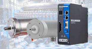
The enduring popularity of core-less brushed DC motors comes from a combination of their simplicity of design, fast transient responses, negligible iron losses, and ease of control.
With speed proportional to applied voltage, the motor can be simply driven using a continuous linear regulation power supply.
But is this always the best solution?
From robotics and industrial automation to electrical appliances and even toys, there are many applications for brushed DC miniature motors that demand driving the motor at more than one load point or through specific load cycles.
While this can be achieved with continuous linear regulation power supplies, these tend to be inefficient and bulky – two characteristics which are particular disadvantages in battery powered equipment.
One alternative is pulse width modulation (PWM) voltage regulation. Here the input power to the motor is continually turned on and off at a high operating frequency: the combination of the coil inductance and the motor inertia serves to smooth out the speed, such that the motor behaves as if it is seeing a pure DC voltage.
The motor speed is defined by the duty cycle – the ratio of the on time to the off time of the applied voltage.
Control via PWM voltage regulation addresses the two key drawbacks of continuous linear voltage regulation, with compact drives that are highly efficient.
Output torque can be more precisely controlled and, with correct design, any resulting eddy current effects – an inherent trade-off of using PWM with a motor – can be minimised, allowing the motor to be optimally driven.
The improved efficiency of the PWM drive reduces the heating of electronic components and, in battery powered applications, increases battery life.
The argument for turning to PWM control, then, is a strong one.
However, there are a number of design considerations to take into account when using a PWM drive with brushed DC motors, with parameters such as PWM frequency and duty cycle all having an impact on the performance and lifespan of the motor.
Design considerations
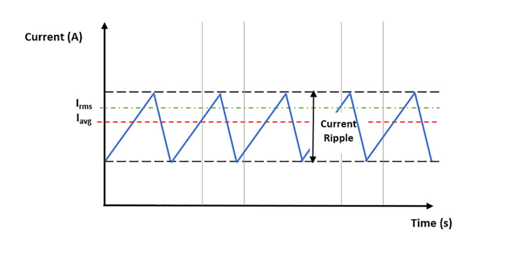
The brushed DC motor can be simply modelled as a series resistor/inductor (RL) circuit. For any such circuit, when voltage is applied across it, the current rises on a curve towards to steady state value.
And when the voltage is removed, the current follows an inverse of the curve towards zero. The time constant of the RL circuit defines the maximum rate of change of the applied voltage in the circuit.
When using PWM to drive the motor, the current across the motor rises and falls with every period of the PWM. Ignoring the back EMF of the motor, the current rise is a function of the motor inductance and total resistance. Ideal design intuition is to decide the PWM frequency so as to allow sufficient time for the current to reach its steady state for each cycle. But it is not always the right approach.
If the PWM frequency is increased beyond this threshold value, there is insufficient time for the current to reach its steady state, and the current oscillates between two non-steady state values, giving rise to current ripple.
The ripple is directly proportional to the applied frequency and as the frequency of the PWM is increased further, the ripple affect reduces to an acceptable range. This current ripple has a number of detrimental impacts on motor performance, including non-linear torque behaviour, since output torque is proportional to current.
Hence, the frequency is chosen such that the torque ripple doesn’t impact the application performance.
Further, resistive heating in the motor winding is proportional to the square of current. Excessive ripple current will increase the heating in the winding pack, so decreasing motor performance and impacting on motor life.
For brushed DC motors that do not use iron laminations, the eddy current and hysteresis losses in the magnetic circuit are directly proportional to the current ripple, so again excess current ripple would reduce the overall performance of the motor.
Current ripple also has a direct impact on the commutation of the motor. For precious metal commutation, electro-erosion of the brushes during the current spikes can be a serious issue, with electro-erosion being proportional to the square of the effective current through the winding. Brush wear already represents the dominant failure mode in brushed DC motors, and increased electro-erosion will only accelerate their wear.
For carbon brush commutation, high levels of current ripple increase patina accumulation – the copper oxide layer formed on the commutator surface of the carbon brush.
While a thin film is advantageous in improving the commutation and reducing the friction, as the film size increases the brush contact will deteriorate.
At moderate to high speeds this might not affect the motor performance significantly, it would certainly begin to have a noticeable effect at lower operating speeds.
Reducing ripple current
Given that ripple current has such an impact on performance and on the lifespan of the motor, how do we minimise it? It should be noted, first, that current ripple is maximum when the duty cycle is 50%, so the goal should be to run the motor away from the 50% duty cycle.
Further, as we have seen, ripple current is directly linked to PWM frequency. It is certainly advisable to keep the PWM frequency outside the range of human hearing (20Hz – 20kHz) as a current ripple in that frequency range may introduce noise during motor operation.
But if we consider that a benchmark target is to reduce current ripple to less than 10% in order to optimise performance and maximise motor life, this can mean a PWM frequency range as high as 40-120kHz.
Portescap recommends engaging with a knowledgeable engineer to discuss the application specifics, as the interdependencies between the requirements of the application, the performance characteristics for the motor and the resulting design or specification of the PWM drive are complex.
Getting a firm grasp on these dependencies becomes even more important in battery powered applications, where the requirement to maximise application performance comes hand in hand with the need to extend battery life.
Dr Sunil Kedia is Core Market NPD Manager at Portescap.