 Engineer News Network The ultimate online news and information resource for today’s engineer
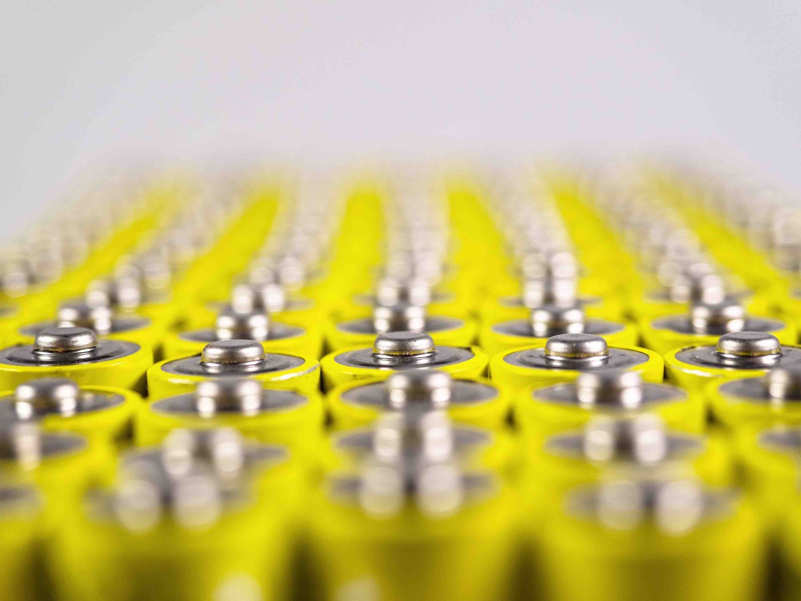
Energy storage devices such as lithium-ion batteries play a crucial role in electromobility and energy transition. In order to optimise battery production, sensors are required to monitor the production line, including thickness measurement sensors. But what are the challenges in making reliable thickness measurements, asks Glenn Wedgbrow
The growing demand for energy storage devices such as lithium-ion batteries and fuel cells are being met by Giga factories that are equipped with efficient, highly automated production technologies.
In order to optimise battery production, sensors are required that monitor the production line to the highest accuracy and dynamics. These sensors include high precision distance sensors, infrared temperature measurement technology, as well as 2D/3D profile sensors for the many measurement tasks involved in battery production such as electrode manufacturing, assembly and forming processes.
In battery production, one of the key quality control parameters is the thickness (and width) of film and strip materials, wet layers and electrode coatings. These require sensors that measure thickness reliably as the material is being processed (inline), helping to optimising production yields while minimising waste. All manufacturers will have a process specification that they will need to meet in order to satisfy their customers. But in reality, how can a manufacturer be sure that they are meeting these specifications at all times and what are the challenges they face?
A number of different measurement systems can be used to measure the thickness of a material. Some of these are used offline, i.e. random samples of the material are removed from production and measured to verify that they meet the specification. A more effective approach is to install an in-process or fixed, inline non-contact measurement system that continuously measures the thickness of the material as it is processed. If measurements from these systems move towards the outer limits of the specification, machine and process control parameters can be altered to bring the thickness back into acceptable limits.
Real-world errors
A key factor to consider when selecting a suitable system from a supplier is to understand the combined real-world errors that can occur when using a non-contact thickness measurement system and how these errors can be eliminated or compensated for. While many suppliers state on their datasheet that the measurement system meets a certain resolution and linearity, in the real world, this performance is affected by a number of environmental influences. Errors associated with real-world thickness measurement are not always so obvious, but can combine to create significantly large errors. It is therefore critical to select a system based on system accuracy, not just sensor accuracy.
Alignment and target movement
Special attention must be paid to the alignment of the sensors, which are typically installed opposite one another. No misalignment, tilting or inclination of the sensors relative to the target object is permissible in order to ensure the sensor spots are measuring at the same point all the way through the measurement range. For example, for a misalignment of 1mm and an inclination of 2°, there will be a thickness measurement error of 35µm. In the case of a 10mm target thickness, this error increases to 41µm.
Combined linearity errors of up to 8µm, for example, can be seen with a vertical target movement of just 200µm of the target in the measurement field even if the target has the same thickness. The combined error of non-linearity from both sensors must therefore be compensated for. As a supplier of non-contact inline thickness measurement systems, Micro-Epsilon has developed its own methods of precise sensor alignment and patented algorithms for this process.
Synchronisation
In order to avoid thickness calculation error due to movement of the target, both sensors must be perfectly synchronised so that they perform the measurement at the same time, at the exact opposite point of the target. If synchronisation does not occur, inaccurate measurement data is produced. For example, if measurements are taken at different time intervals, micro-vibrations of the target or of the sensor mechanics will result in a thickness measurement error. For example, for a time-delayed measurement of 1ms, a deviation of 125µm is produced (assuming 1mm vibration at 20Hz).
Individual sensor accuracy/linearity
Each measurement sensor has its own measurement uncertainty, often referred to as ‘linearity’. This means that at any given point in the measuring range, the actual reading from a sensor can vary by a percentage of its measuring range. The challenge is that no sensor is the same, so errors caused by non-linearity can add or subtract in the final result. Micro-Epsilon has overcome this challenge by performing a combined, patented calibration of both sensors to create a new significantly improved thickness measurement linearity.
Thermal behaviour of sensors and/or mounting frame
It is extremely important to design a mechanically and thermally stable sensor mounting frame. The mounting mechanism should be isolated from process or machine vibration as best as possible. Mounting with an O-frame is more stable than using a C-frame.
Thermal expansion of mounting materials is often overlooked as a source of large errors in precise thickness measurement. Therefore, selecting materials with as low a thermal expansion coefficient as possible is very important. For example, mounting sensors on a typical aluminium or stainless steel extruded profile, with a thermal expansion coefficient of ~16ppm/K, experimental testing has shown that just a 5°C change in ambient temperature can move the sensors by >80µm! In contrast, using a standard grade Invar mounting frame with a thermal expansion coefficient of typically 1.2ppm/K reduces this to 6µm. Specialist Invar grades can reduce this error by half again, but can result in a very expensive solution and does not solve the problem when the manufacturing tolerances can be single microns, as is often the case with battery production. Micro-Epsilon has solved this issue with integrated automatic thermal compensation to eliminate measurement errors due to thermal expansion.
In addition, Micro-Epsilon inline thickness measurement systems provide automatic calibration features built into their system as standard, which provide gauge capability results at the touch of a button. This also means the operator does not have to spend time calibrating and checking the system.
Glenn Wedgbrow is Business Development Manager at Micro-Epsilon UK.