 Engineer News Network The ultimate online news and information resource for today’s engineer
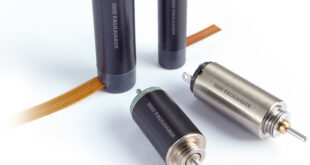
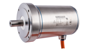
Mini motor applications utilise DC motor technology because of compactness, low weight, and reliability. Stopping, slowing or holding the position and load of these motors is crucial for many applications from controlling robotic joints through to automated window shades. This control is achieved by integrating an electromagnetic brake, accurately specified according to the application requirements and parameters of the DC mini motor. Louis Mongin explains the technology behind electromagnetic brakes for DC mini motors.
In miniature DC motor applications, electromagnetic brakes are used to hold, stop or slow down a load. Without a brake, a motor would continue to rotate without control even after cutting its supply of voltage or current; or it would fail to hold position against a competing power. While alternative torque control devices could be used, electromagnetic brakes can combine precision with a compact, reliable, energy efficient and cost-effective design.
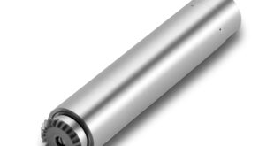
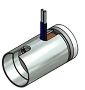
To hold a DC mini motor in position at a specific stopping point across a variety of industrial and medical applications, the general design includes a fixed field coil that acts as an electromagnet to generate torque to brake or hold the load. The coil’s electromagnetism controls an armature that either engages or disengages with a structure. The design of the brake mechanism features a hollow shaft mounted onto the shaft of the DC motor, which gives compact integration.
Brakes are available in a power-on design, which means that the brake is only engaged when current flows in the field coil. This is acceptable when the brake doesn’t have to hold a high load, or if holding torque isn’t required after power-off. Alternatively, with a power-off brake, the brake remains engaged at all times unless the current is flowing in the electromagnet, which creates an inherently safer design for some applications.
Spring-set brakes utilise power-off braking and are used to automatically stop and hold a load in the event of a power failure or emergency stop situation. In this design, braking force is applied through a compression spring, and the brake is usually released by manual control. The advantages include repeated braking cycles from full motor speed with no torque fade, and the designs can be customised in aspects such as voltage rating and dynamic friction material according to the spring force requirement. The disadvantage of a spring brake is that they can present backlash, affecting the precision they can offer for dynamic braking or position holding.
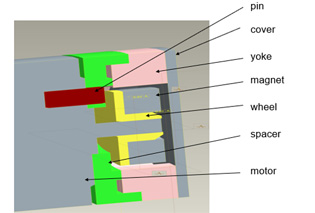
Instead, for applications where dynamic stopping and holding a moving load is required, as well as for high cycle rate stopping, a permanent magnet power-off brake should be used. In this design, brakes are engaged magnetically and disengaged electrically, providing safe load holding in power shut-off. When voltage or current is applied to the brake, the coil becomes an electromagnet and produces magnetic lines of flux counteracting those of the permanent magnet. This action releases the armature, creating an air gap and allowing the load shaft to rotate. Increasing voltage or current also enables braking force to be controlled with precision, as opposed to the spring brake’s on/off functionality.
As the permanent magnet brake design includes no moving parts, they can operate at very high speeds. Unlike spring breaks, they don’t allow backlash, because the design includes a fixed connection between the armature, spring and hub. This allows them to be controlled with precision. As heat is generated during dynamic braking, this means that the brake must be correctly sized to deal with friction, load and torque requirements. Permanent magnet brakes require consistent and specific current, meaning that these brake designs should be carefully considered before using them in conditions that could cause current fluctuations, such as high or changing temperatures.
Thanks to the precision control of a permanent magnet brake, they are well suited to use in robotic arm joints. Their zero-backlash capability means they can precisely hold torque and also provide dynamic stopping. An example of a DC mini motor application that requires safety in holding torque is the control of automated window shades. Providing automatic operation, the power-off brake also allows the motor to hold the shade position when power is removed.
Portescap’s engineers regularly integrate DC mini motor braking solutions into bespoke OEM applications. The team ensures exacting sizing and specification, as well as recommending the most effective technology and features for specific requirements. Design is combined with rapid prototyping and testing to ensure safety and precision, before moving the development to volume production.
Louis Mongin, BLDC Product Strategic Manager at Portescap.