 Engineer News Network The ultimate online news and information resource for today’s engineer
Centralised systems offer higher levels of control and redundancy, says John Stark
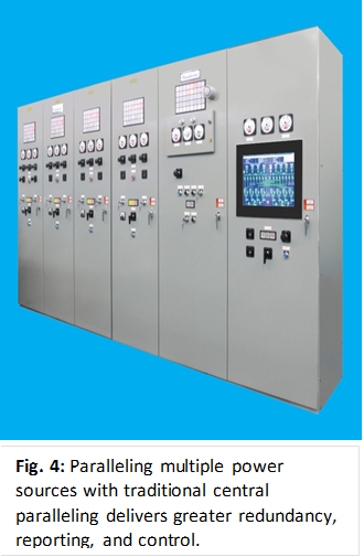
Many facilities run several generators in parallel to ensure power reliability and guarantee sufficient emergency or backup power.
Paralleling generators in this way improves reliability, increases load management flexibility, manages run time on engines and provides maintenance flexibility reducing generator costs.
Synchronising engine generators to a common bus, operators can use either onboard paralleling (in which controls are integrated into the generator design and mounted on each generator) or traditional central paralleling (in which controls are located either in the paralleling switchgear or as a separate control switchboard located in a separate location, away from the engine generators).
While each has its advantages, traditional central paralleling distributed energy controls provide superior backup redundancy, better reporting, and a higher level of control – all in a clean and quiet control room or switchgear room environment.
Brief overview of paralleling
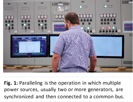
Paralleling is the operation in which multiple power sources, usually two or more generators, are synchronised and then connected to a common bus. The combination of protection, metering, control, and switching elements act as an integrated system to control the distribution of power for the following:
- Emergency systems
- Legally required standby systems
- Critical operation power systems (COPS)
- Optional standby systems such as emergency transfer and load management systems1.
Before being paralleled, the frequency, voltage, phase angle, and phase rotation of all the sources must match or an out of phase condition causing an overcurrent fault could occur.
Paralleling controls refer to the controls and switching apparatus that manage the generators to ensure proper voltage, frequency, and phase angle for synchronisation and alignment prior to closing the generator breaker.
Options for paralleling switchgear
There are two main options for achieving the necessary synchronisation: onboard paralleling and central paralleling.
Onboard paralleling
With onboard paralleling, the generator controls are built into the engine generator mounted controller, physically mounted on the generator unit. Each engine is connected to the generator on a skid with the control panel located on that same skid, replacing controls and metering that would be located at the paralleling switchgear.
The engines start up on their own and ‘talk’ to each other, much like singers who listen to each other, get in harmony and match the sound. They are paralleled onto a common main bus by closing local generator breakers or by signalling the remote switchgear generator breakers to close.
Onboard paralleling controls are provided with the generator by a single manufacturer, which may reduce lead time and commissioning time.
Expansion is easy, provided that any additional engine generators are the same manufacturer as the existing units: simply add a new generator and the newcomer will automatically join in the harmony and talk to the others. Onboard paralleling controls simply add the synchronisation function to the engine controllers.
The simplicity of onboard paralleling makes it a cost-effective solution, especially for non-critical applications such as hotels, retail, and more.
However, there are several disadvantages, especially in the event of an emergency.
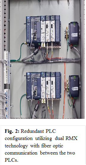
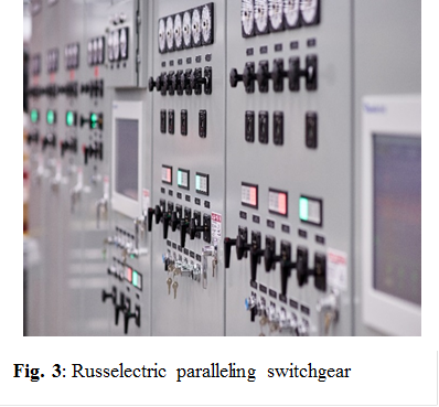
Fig. 2 shows the arrangement of redundant PLC controls. With Onboard paralleling controls there are no redundant controls and no manual controls so manual synchronisation is not possible. Fig. 3 shows an example of centralised paralleling controls and metering located at the paralleling switchgear.
Metering at the switchgear, with ‘onboard’ paralleling is all done on a single screen with no discrete metering. Annunciation is also all on this same screen, with no annunciation at the switchgear. Therefore, if the screen or communication fails, there is no means to monitor the generator system at the switchgear location.
Emergency generators are typically diesel and are usually located in engine rooms or in their own outdoor enclosures; and therefore are not an ideal environment for control systems and/or operations.
Generators are subject to stresses in the hot and dirty environment, in which oil and diesel fuel may contaminate surfaces.
Since engine generators require a high volume of intake air for combustion and cooling, louvres are provided to allow non-filtered, outside air to be drawn in across the engine generators, bringing in particulates that can adversely affect the integrity of the controls. It can also be a challenge to read the local screens usually paired with the onboard control panel.
If one engine runs erratically, it must be separated from the others by opening the generator breaker, which is difficult with onboard controls. With centralised analog metering, one could identify instability of one of the machines without going out to each individual engine.
Going to each individual machine makes it difficult to troubleshoot problems, pinpoint the cause of issues, or qualify exactly what the problem might be versus a centralised location for the controls and being able to put the system in manual to operate the system manually.
Centralised event reporting, with time stamping is not standard with ‘On-Board’ paralleling. Dead bus paralleling is done only using a token passing arrangement. This logic is dependent on communication between the engine generators. Switchgear paralleling systems provide redundancy for dead bus closure and the sensing is within the switchgear, as opposed to relying on communication between the individual generators.
And while greenfield sites pose no generator ‘vendor matching’ issues for an onboard paralleling scheme, during expansions of existing sites, that may not be the case. Bringing in additional generators may require selecting different manufacturers and introduce difficulties synchronising the new units with the existing onboard paralleling controls.
Centralised paralleling
Paralleling switchgear centralised controls are usually located in a separate room. A Programmable Logic Controller (PLC) controls the system automatically using a microprocessor and computer-based controls, taking the signals from the generators and annunciating them in the control room.
Centralised paralleling controls are most commonly found in data centers, healthcare facilities, and a wide range of other mission critical facilities. Their use can greatly aid in troubleshooting efforts by allowing operators to find the problem from a central location.
The operator can review and query events that are recorded and time stamped to help troubleshoot the problem and provide the operator with historical information.
With this approach, operators can have manual control for back-up redundancy, and have access to discrete metering and control components. They can operate and monitor the entire system of paralleled generators in a centralised, clean, and quiet control room environment. They view information on larger and more elaborate touchscreens rather than having to navigate in a noisy engine room environment trying to read oil-smudged screens.
In addition, operators have access to centralised reporting at all times so they can always be apprised of what is going on with the individual engine generators, and the system as a whole. If an engine runs erratically, operators can make changes either electronically or manually, providing a higher level of localised control over onboard systems. Reporting capability (both current and historical) is much more comprehensive.
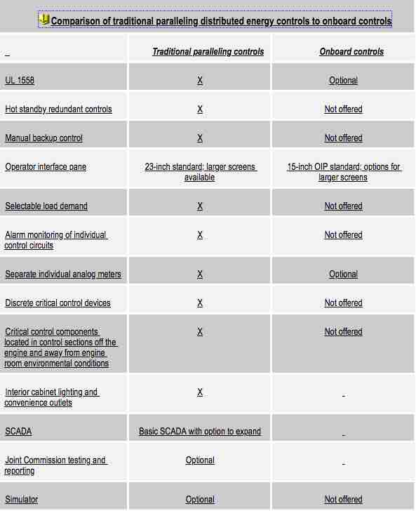
The accompanying table compares key features of traditional paralleling distributed energy controls to those available with onboard controls.
Comprehensive power control systems available
Russelectric offers paralleling control switchgear for both low and medium voltage. These systems are built under UL 1558, the highest standard available, for low voltage switchgear and UL listing for ‘Circuit Breakers and Metal‐Clad Switchgear over 600 Volts (DLAH)’, for 5KV and 15 KV switchgear. This is important to note because manufacturers of onboard controls often provide lower quality switchgear that conforms only to UL891, which is not a testing standard.
The Russelectric systems feature dual redundant, hot backup PLCs utilising a ring redundant communications network for the switchgear distributed I/O.
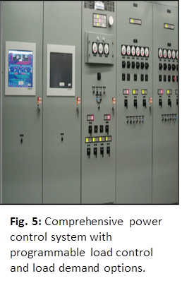
The switchgear comes standard with a variety of programmable load control and load demand options all preprogrammed to meet a variety of needs. Control circuits are individually protected with circuit breakers that are monitored by the PLC.
If a breaker trips for whatever reason, the PLC sounds an alarm and the tripped circuit breaker is logged in the event log with a date and time stamp.
All alarms and functions are monitored and logged in the event log with time and date stamp. The log can be queried using different criteria for complete diagnostics of the system.
Discrete components are utilised throughout for critical control functions. The controls incorporate separate control components for primary functions such as automatic synchronising, sync check function, utility grade protective relaying, metering and control switches.
Many of these discrete control and monitoring devices are utilised with industrial control and selector switches on the switchgear doors to provide fully redundant manual control capability in the unlikely event of a catastrophic failure where both PLCs are non‐functional.
The Russelectric central power control systems can also interface with microgrids, which provide the integration of renewable, alternative energy power sources such as solar, battery storage, fuel cells and wind with onsite engine generators.
Reliability and redundancy
Although, onboard paralleling can be a lower cost solution for paralleling generators, it does not provide the kind of reliability and redundancy needed by mission critical facilities.
To achieve fully redundant automatic and manual control capability and maximise reliability, central paralleling distributed energy controls are the clear choice.
John Stark is with Russelectric.
References: 1. Paralleling Switchgear by Maurice D’Mello, P.Eng. Systems Engineer, GE Consumer & Industrial, Canada.