 Engineer News Network The ultimate online news and information resource for today’s engineer
Both eddy current sensors, as well as inductive switches and displacement sensors each, have their respective advantages when measuring position and displacement of objects in harsh environments. However, recent advances in eddy current sensor design, integration, packaging and overall cost reduction, have made these sensors a much more attractive option, particularly where high linearity, high-speed measurements and high resolution are critical requirements, says Glenn Wedgbrow
In order to appreciate the inherent advantages of eddy current sensors relative to inductive switches and displacement sensors, it is important to first understand the operating principle of both types.
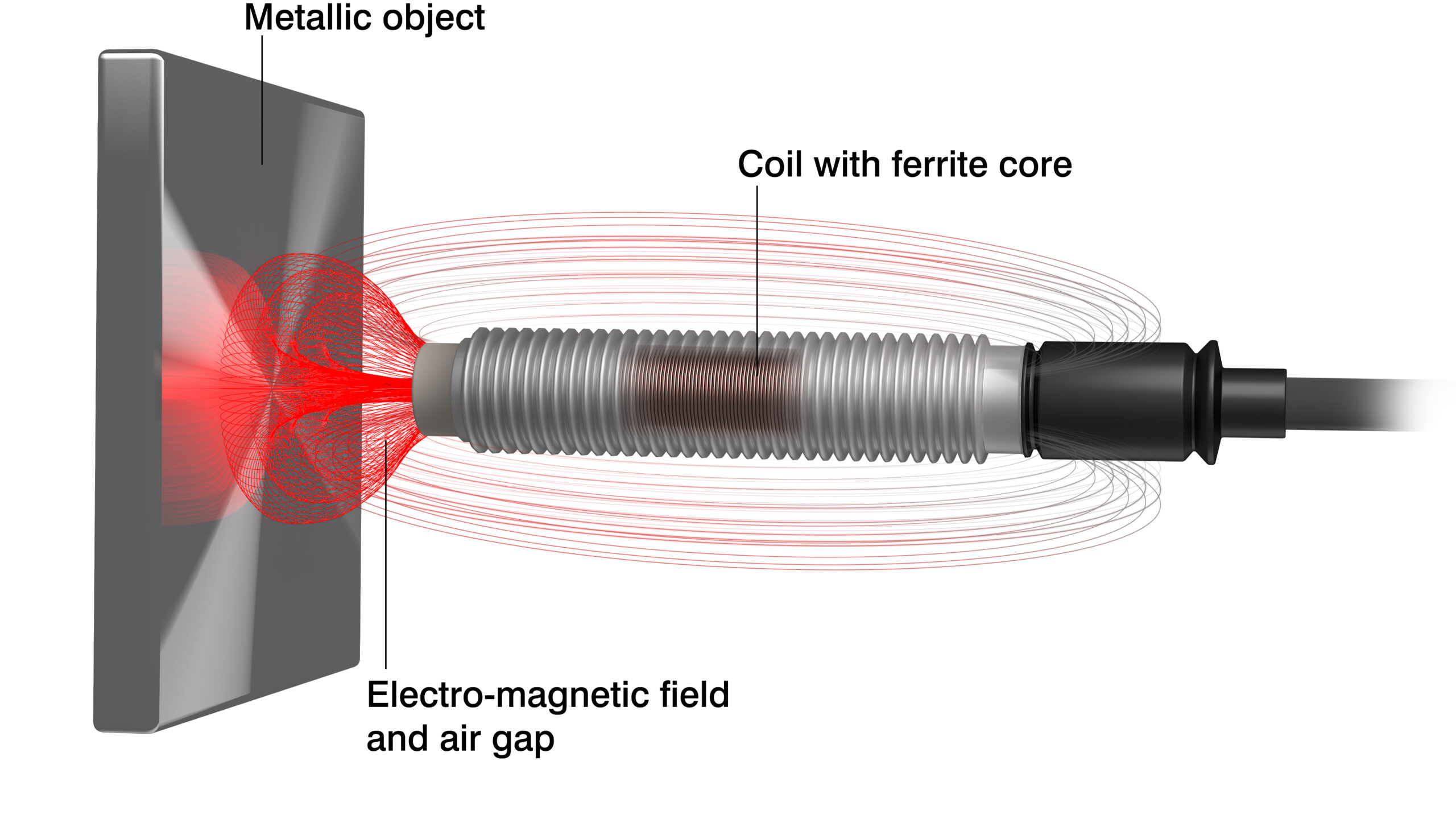
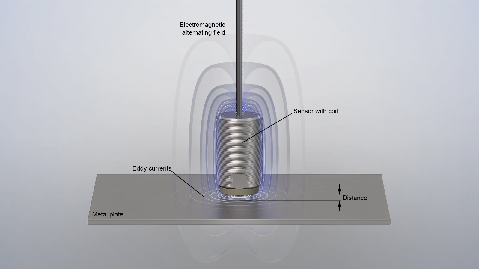
The classic inductive displacement sensor comprises a coil that is wound around a ferromagnetic core. When excited by an alternating current from an oscillator-based driver circuit, the coil generates a magnetic field that is concentrated around the core. The lines of flux interact with the target conductor as it approaches, creating eddy currents that are the reverse of the initial excitation current and have the effect of reducing the voltage across the oscillator. These variations in voltage due to the change in air gap distance are detected and converted to an analogue output signal, such as a 4-20mA loop, and then processed upstream to determine displacement.
In an inductive displacement sensor, a coil is wrapped around a ferromagnetic core and when an alternating current is passed through the coil it generates a magnetic field. The lines of magnetic flux interact with a conductive object as it gets closer and generates opposing eddy currents, per Faraday’s Laws of magnetic induction. The eddy currents push back against the excitation current to cause a drop in voltage in the oscillator and it’s this drop in voltage that is used to determine displacement.
A proximity sensor, also called a proximity switch, is a simplified application of the principles behind the induction effect, detecting only whether or not an object (the conductive target) is present or not. A comparator (Schmitt trigger) detects the drop in voltage and sends a signal to an amplifier. This in turn switches the output in a binary fashion. The output can be normally open (NO) or normally closed (NC), depending on the user’s choice of configuration.
Because of the ferromagnetic core in an inductive displacement sensor, the output is non-linear and so it needs to be linearised either in the sensor electronics or mathematically using polynomials in the plant or machine control system.
Along with non-linearity, another downside of using a ferromagnetic core is the “iron losses” due to the core itself absorbing the magnetic field. These losses increase with frequency, to the extent that an inductive displacement sensor maxes out at around 50 measurements per second.
A third problem with inductive displacement sensors is poor tolerance of wide temperature variations because of the high thermal coefficient of expansion of the ferrite core material. This wide variation makes temperature compensation very difficult, usually resulting in a large thermal drift of inductive displacement sensors.
Eddy current sensors offer improved precision
To overcome these limitations, a certain class of inductive displacement sensor called ‘eddy current sensors’ have been developed which rather than a ferrite core, use an air-core coil.
Eddy current sensors employ the same laws of magnetic induction as inductive displacement and proximity sensors. However, the use of an air-core coil along with advanced electronics, manufacturing and calibration techniques, puts them in a much higher performance category
While the eddy current sensor’s operating principles are in line with Faraday’s Laws, it is the eddy currents’ effect on the impedance of the coil that is measured rather than the oscillator’s voltage change. The controller calculates the impedance by looking at the change in the amplitude and phase position of the sensor coil.
High-performance sensing with eddy current sensors
While all the sensors mentioned above are able to detect targets such as metals and ferromagnetic and non-ferromagnetic materials in harsh, non-contact environments, the eddy current sensor’s architecture, as well as advanced electronics, manufacturing and calibration techniques, put it in a much higher category in terms of performance.
These performance characteristics can be broken down into two categories: inherent characteristics and characteristics resulting from product design, manufacturing and calibration. The three most exciting inherent features are:
- A very high measurement frequency of up to 5kHz
- High resolution, down to 0.5µm
- High linearity and temperature stability
Because of the use of an air-core coil versus a ferrite core, an alternating current of up to 1MHz can be used, although the electronics in devices such as the eddyNCDT3001 and NCDT3005 provide measurement frequencies of 5 kHz. This is still 10x that of their inductive displacement counterparts which typically top out at 50 Hz (translating to 50 measurements per second). Higher-end Micro-Epsilon eddy-current sensors can reach 100 kHz.
In terms of linearity and temperature, the air-core coil does not have to deal with the flux losses or compensate for the thermal expansion of a ferrite core, so it has a 10x improvement in linearity. This linearity is also the result of Micro-Epsilon’s manufacturing and calibration process, whereby the coil is placed in an oven and cycled between -20˚ and +60˚C. The changes in the material are stored in the calibration set-up in the sensor and used to compensate for temperature fluctuations.
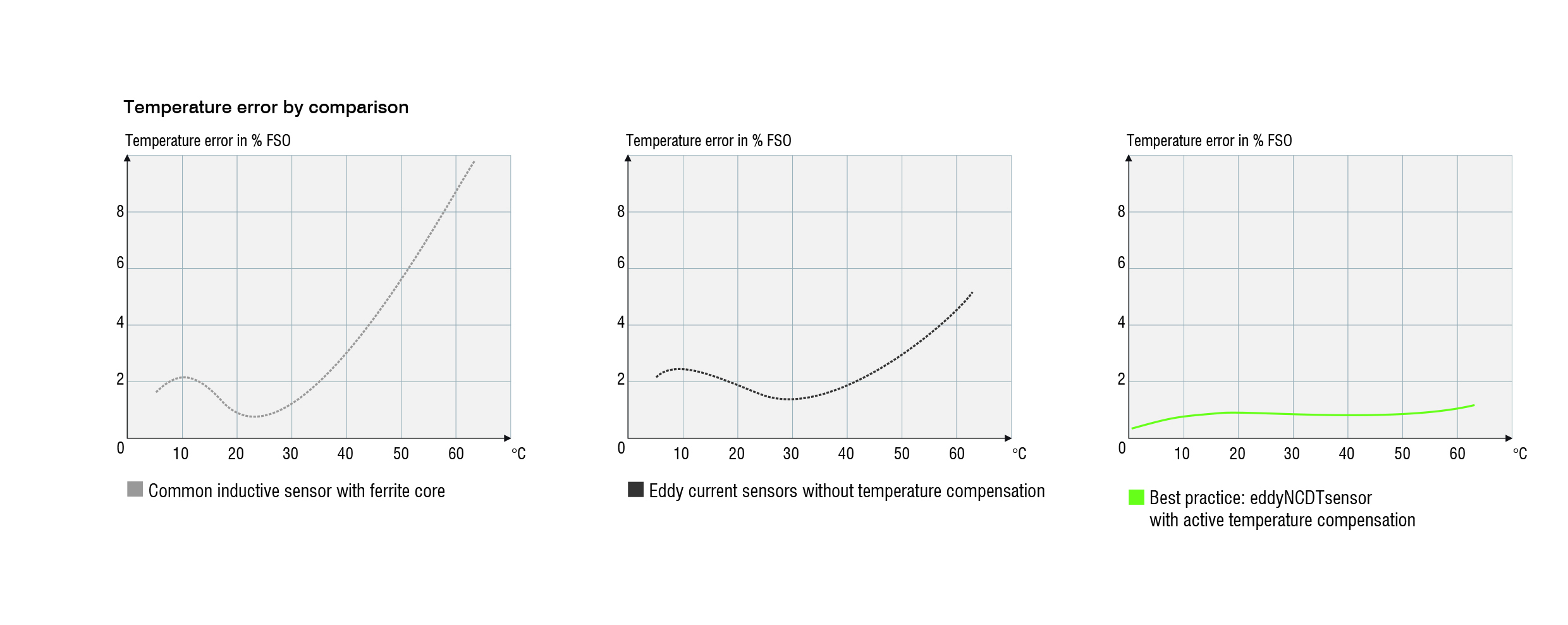
Temperature cycling of the sensor and then storing its response to enable temperature compensation in the field are key steps during manufacture and production. These are what give Micro-Epsilon sensors high stability over wide temperatures ranges, over the full scale of operation
While some inductive displacement sensors also have compensation built into the sensor, it’s typically limited to plus-or-minus 3 – 5% of the full-scale output (FSO). Eddy current sensors provide compensation for the full measurement channel (± 0.025% FSO.) It’s also important to note that eddy-current sensors are calibrated to the target material at the factory for maximum accuracy, which puts a higher premium on these devices.
Benefits of eddy current
- Non-contact measurement of displacement, distance and position on ferro- and non-ferromagnetic materials
- High resolution and temperature stability
- Temperature range -40°C to 200°C and higher
- Robust and reliable sensors IP67
Eddy current sensors eliminate packaging and housing limitations
Both proximity and inductive displacement sensors can be housed in solid metal (food compatible, high resistance grades). Eddy current sensors’ operating principle means they must use a non-metallic cap. Despite this, Micro-Epsilon eddy current sensors are still certified to IP67. In addition, the packaging of eddy current sensors has been advancing rapidly, with the electronics being integrated into the device.
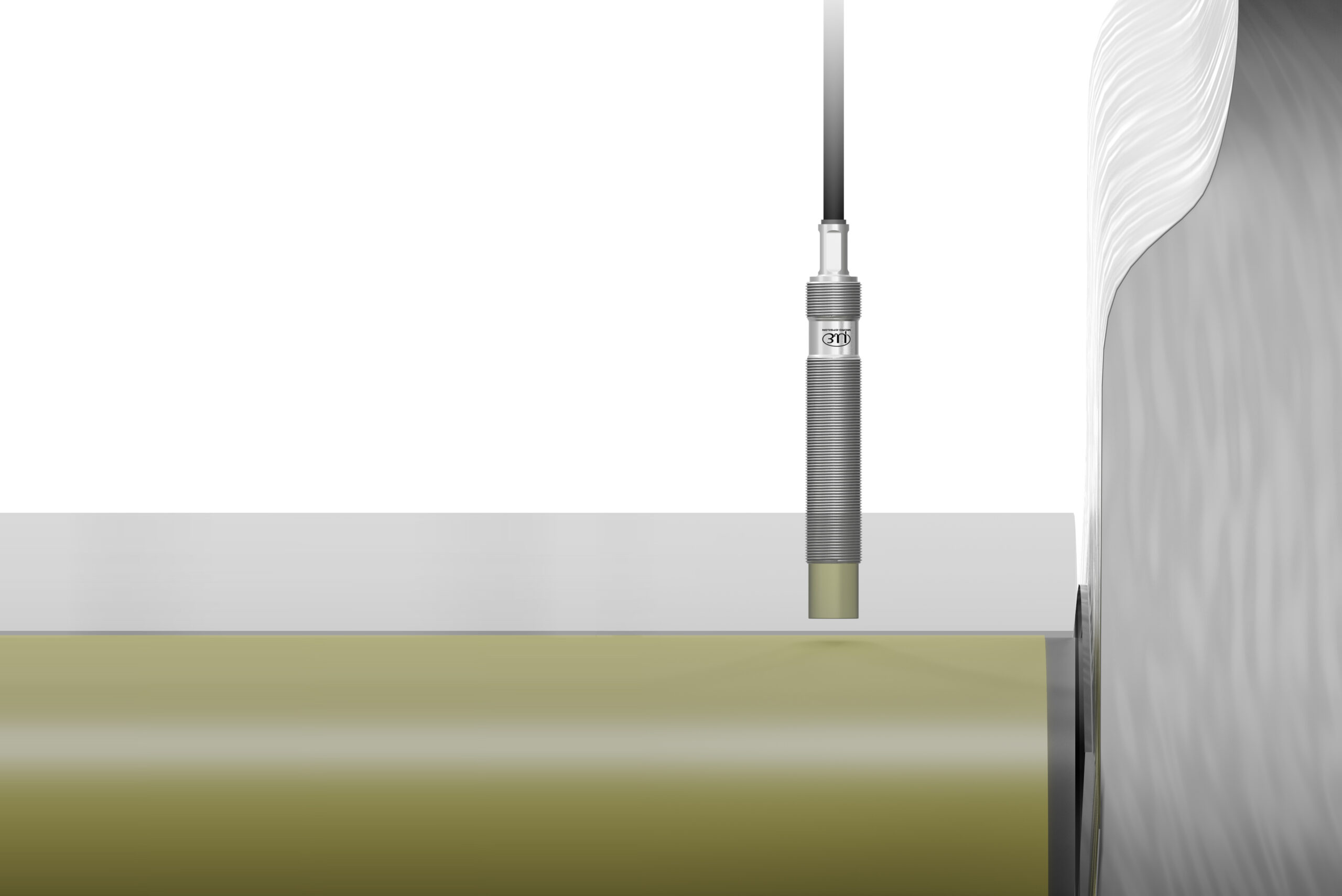
Most significantly, the eddyNCDT 3001 product line signifies a new class of eddy current sensors that come in an M12 housing with both the integrated controller and signal-conditioning unit. This makes them much more amenable to standard mechanical formats and requirements, as well as making them a more attractive replacement option for inductive displacement sensors. The new eddyNCDT3005 from Micro-Epsilon has separate compact electronics which enables many different sensor measuring ranges to be packaged with compact ‘in-cable’ M12 electronics. Other characteristics include the ability to withstand up to 300 bar of ambient pressure. Also, the voltage output is the same as inductive displacement sensors, covering the full 0.5 to 9.5V, making them fully comparable on a 1:1 basis.
Applications and usage
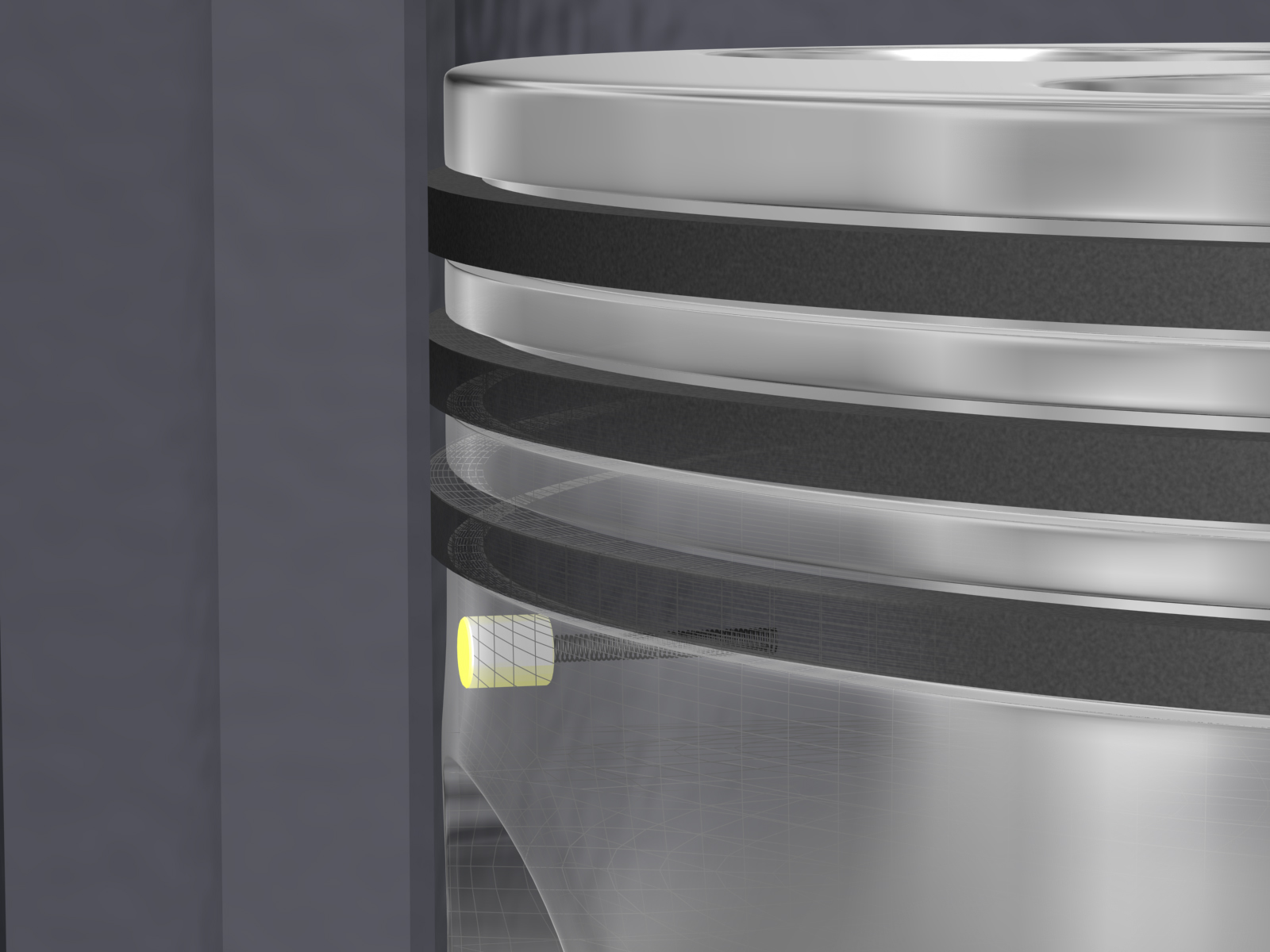
The high cut-off frequency of eddy current sensors enables metrological detection of distance values even in high-speed processes such as machine tools and crankshafts. IP67 protection ensures they can also be used in harsh industrial environments where dirt or humidity will not influence the measurement result. A classic example is monitoring the lubricating gap in a combustion engine.
Custom sensor designs for specific needs are possible, including specific target object calibration, mounting options, individual cable lengths and modified measuring ranges, as well as pressure tolerance to 2,000 bar.
When using eddyNCDT sensors, care must be taken to ensure they are placed as close as possible to 90˚ relative to the target surface in order to achieve the highest resolution and measurement accuracy. Sometimes an exact right angle mounting of the sensor to the target is difficult or impossible.
In such cases, the measured values will deviate marginally from those acquired at a right angle, so use the sensor supplier’s graphs to factor in the effect of a tilted sensor. For example, with a 4mm sensor and an aluminium target, an inclination of ±4 degrees can be accepted and neglected in most applications. For placement, note that the use of an air-core means that the distance from sensor head to target should be 4 mm or less.
Glenn Wedgbrow is Business Development Manager at Micro-Epsilon UK.