 Engineer News Network The ultimate online news and information resource for today’s engineer
As many industry sectors demand smaller and smaller parts and components, the requirement for thin planar optics is growing exponentially. There is a need to supply optics that are flat and free from deformities which can effect end use functionality. Dan Musinski looks at the demands placed on metrology tools when measuring such optics to assess they are fit for purpose
Driven by the demand for smaller and smaller consumer products and semiconductor devices, manufacturers require thin planar optics for an array of applications. This puts the responsibility on the material and optics manufacturers to ensure the glass is flat and free of material deformities which can cause distortion and affect end-use functionality.
This places a huge burden on metrology tools that need to measure and confirm the uniformity of thin planar optics thereby proving that they are fit for purpose.
Inherently, the measurement of thin parallel optical surfaces can be extremely taxing. Such optics are characterised by the fact that they are less than a few millimetres thick, and this means that the front and back surfaces are very close together.
Because of this, standard mechanical phase shifting interferometry (PSI) finds it difficult to discern between the surfaces.
A more advanced solution is Fourier-transform phase-shifting interferometry (FTPSI), which enables easy characterisation of the front and back surface, optical thickness variation, and material homogeneity of thin plane parallel glass.
FTPSI makes it possible to distinguish between the front and back surfaces and characterise the quality of both in a single measurement, even if they are less than a millimetre thick.
Why FTPSI?
To understand why FTPSI is the preferred technique for measuring thin parallel optics, we need to take a closer look at the alternative traditional measurement techniques and see where they fall short.
If we consider PSI which works by passing a light beam through an ideal reference optic (called a transmission flat [TF]), to the part under test, we see that this technique cannot distinguish between the front and back surfaces of a thin parallel optic.
When properly aligned, the TF and the part under test create an interference pattern, recorded as an interferogram.
The metrology software analyses the height variations produced by the phase shifts and reconstructs the surface wavefront, which represents the difference in height between the TF and the test part.
When the front surface of a thin, parallel part is aligned, a second reflection is typically returned to the interferometer from the back surface. This results in a complex fringe pattern created by multiple, overlapping interferograms that cannot be accurately analysed using PSI. (See Figure 1.)
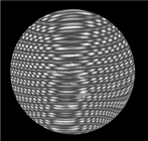
There are actions that can be taken to improve the situation, but they are time consuming and add unnecessary and potentially damaging steps into the overall process. These include applying black paint to the back surface to extinguish its reflection, colouring with a dark coloured marker, or spreading petroleum jelly on the surface.
The FTPSI method negates the necessity to manually manipulate the back surface of the thin optic to undertake meaningful and accurate measurements.
Instead, FTPSI uses the refection from the back surface to gain more information about the thin optical component in a single measurement.
This is possible because FTPSI does not require mechanical motion within the test cavity to create the interferograms.
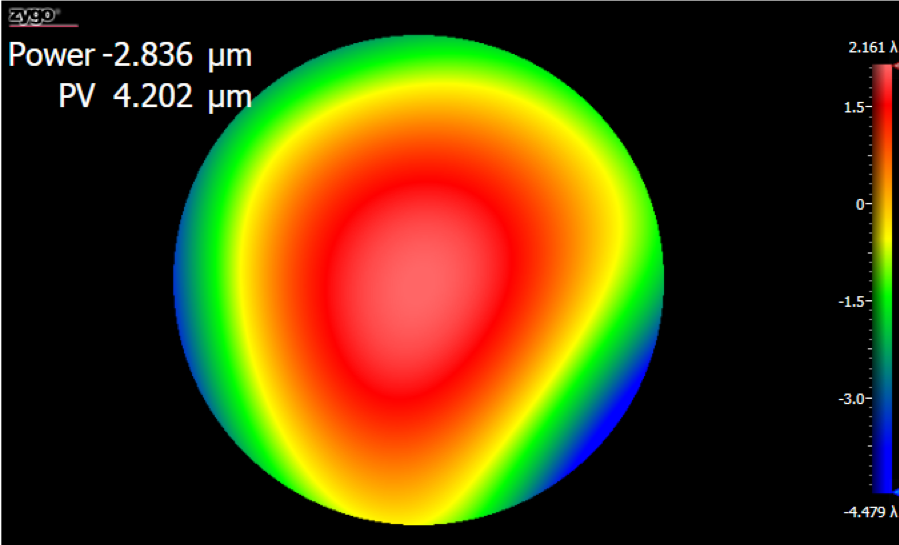
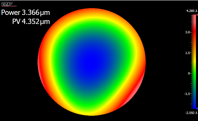
Instead, FTPSI relies on modulation of the wavelength of the laser source to enable the measurement. Each cavity in the optical path in an FTPSI acquisition produces a unique interference frequency that defines its cavity length, and this enables a clear delineation and accurate characterisation of the surface.
Algorithms can then analyse both surfaces and characterise their form independently. (See Figure 2)
Three- and four-surface FTPSI
Let’s start with the basics. A TF – as mentioned above – is used with an interferometer to establish a plano reference for a surface or transmitted wavefront measurement.
A reference flat (RF) is a high-quality optical surface that is used to direct a measurement beam with minimal effect on the overall wavefront.
The simplest FTPSI measurement is a three-surface configuration that consists of the TF – surface one ‚ and the test part – surfaces two and three (see Figure 3).
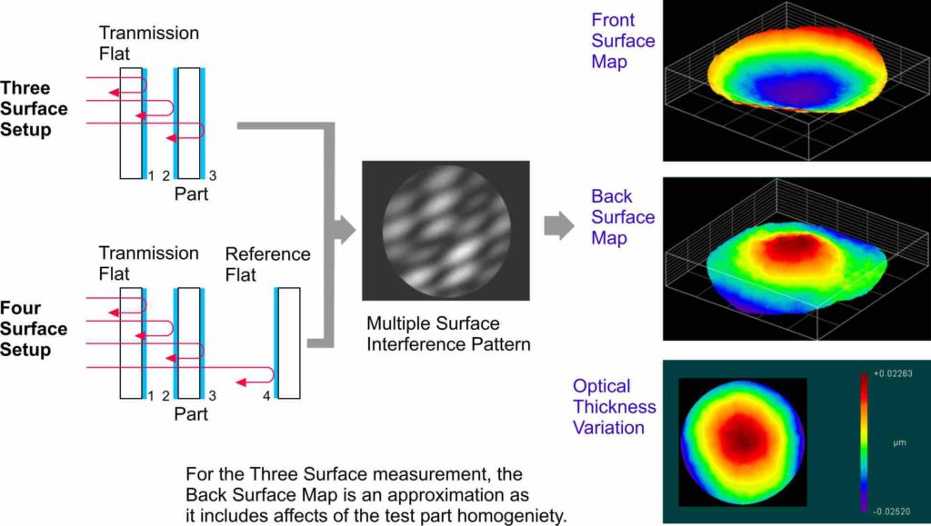
In this configuration, a back-surface result is provided but it includes material non-uniformities due to the measurement beam passing through the material of the test part.
For higher accuracy measurements of the back surface, a four-surface configuration can be used by placing a RF – surface four – behind the test optic. In this configuration, the form of surface three is compared to the known RF. This configuration creates a second test cavity between the back surface and the RF and provides a direct measurement of the back surface without the uncertainty of the material in the part.
A single FTPSI measurement with both the three- and the four-surface cavity configurations includes a thickness deviation result, which is a full-surface map of the material thickness across the test part.
Material homogeneity
The four-surface cavity configuration described above enables the characterisation of the material homogeneity of the test part, a unique feature of the FTPSI technology.
The homogeneity information can be obtained by first measuring the cavity with the test part inside, then removing the part from the cavity and performing an ‘empty cavity’ measurement, allowing a comparison between the TF and the RF.
Unlike other homogeneity measurement techniques that only provide the nonlinear component, an FTPSI result maintains a fixed cavity and, therefore, can provide both the nonlinear and linear components of the material homogeneity.
The linear portion is critical for applications that are sensitive to beam pointing, as the result can be used to predict how a beam deviates when passing through the test part.
Accuracy
As with all interferometric test methods the measurement uncertainty is based on a number of factors including the quality of the reference optics, stability of the measurement environment and mounting techniques.
For parts less than 6 inches in diameter (150mm) the reference optic peak-to-valley surface form can be of the order of 2.5% of the wavelength of the light used to make the measurement – λ/40.
If the system, for example, has a laser emitting red light at a wavelength of 633nm this corresponds to approximately 16nm. In most cases this enables the resultant measurement to be well within the tolerance bandwidth for thin glass applications.
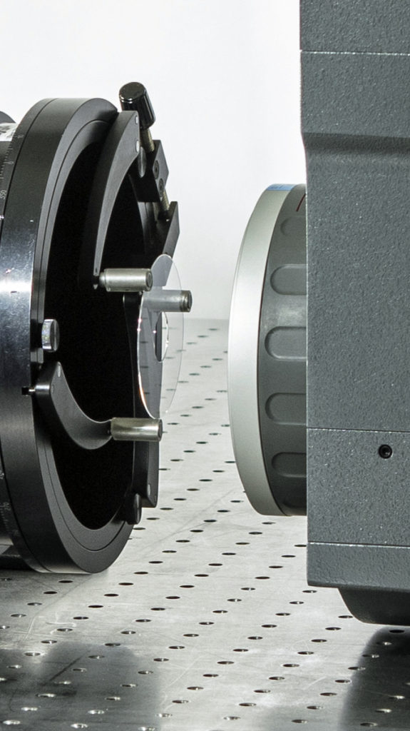
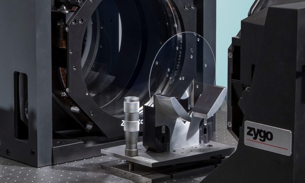
How the part is held in the test cavity is probably the most critical factor when measuring thin optics, more specifically the mounting technique and the mounting orientation.
Simply clamping a thin optic can induce unwanted stress and cause the optic to bend. Differences in orientation can yield very different measurement results, especially for thin parts, due to gravity affects.
Ideally, the part should be mounted in the same configuration in which it will be used in its end-use application to avoid unexpected differences between the designed intent and actual performance. (See Figure 4.)
Summary
FTPSI is a compelling choice for optics manufacturers who need to ensure the quality of thin, parallel optics.
Unlike conventional mechanical PSI, FTPSI can distinguish the front and back surfaces and characterise their corresponding surface information in a single, repeatable measurement.
Thanks to advances in both equipment and algorithms FTPSI can characterise surface form, thickness deviation, and material homogeneity of optics that are less than 1mm thick.
Faced with the growing demand for thin, parallel optics, and the challenges involved in accurately measuring those optics, FTPSI overcomes the limitations of previous methods. Its strength in characterisation along with its ease-of-use makes it a good choice for optical metrology.
Dan Musinski is the Vice President of Strategic Business Development at Zygo Corporation in Middlefield, CT, USA.