 Engineer News Network The ultimate online news and information resource for today’s engineer
While regulations vary throughout the world, the facts about the deterioration of undersea cables do not. The physics remain the same. Any electrical insulation will begin to deteriorate after it is made.
The environment in which the subsea cable lies, however, is particularly harsh and the conditions will almost certainly increase the rate of deterioration. If the subsea cable insulation becomes compromised it increases the risks of equipment failure (and so lost production).
Floating earth systems (IT earth) are commonly used as they promote high availability of the system – a vital consideration for subsea networks. Such systems continue to work even if there is a single fault to ground.
Although systems still operate and production can continue, a second insulation fault can result in dangerously high currents that would at a topside facility be almost certainly fatal on human contact.
A second earth fault can also lead to an accelerated failure of the electrical system through the erosion of the copper conductors as a result of current leakage and the electrochemical reaction of the copper in the seawater.
Measuring insulation resistance (IR)
Subsea electrical failures almost always result from water ingress, which manifests as an IR fault. IR is calculated by measuring the leakage current between conductors and earth. This is made up of three sub-currents: Capacitive charging, dielectric absorption leakage and conductive leakage.
The capacitive charging part of the leakage current occurs because of the close proximity of parallel cables in a subsea umbilical and this quickly vanishes over time. The dielectric absorption leakage current is caused by the polarisation of molecules within the dielectric material and also decreases over time.
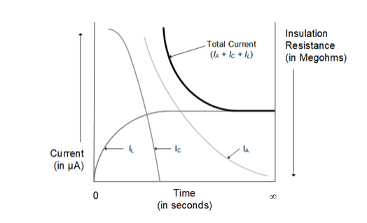
The conductive leakage current flows between conductors or from a conductor to ground. It is this part of the overall leakage current that increases as insulation deteriorates.
So, by measuring the total leakage current over a period and using Ohm’s Law, the operator is left with an IR value, and so a measurement of insulation deterioration over time.
There are several types of IR test. The most fundamental of these is a Spot Test. This is a simple, single test where a test voltage is applied for 60 seconds and then a reading taken. Results are dependent upon time, temperature and interpretation.
To properly interpret this basic test, an operator needs historical data to compare the results in order to evaluate the quality of the insulation.
Time Resistance IR testing is a relative measurement technique which involves taking successive reading at specified times. This method is based on the relative magnitudes of leakage and absorption currents in clean, dry insulation compared with that which has some water ingress or contamination.
If the insulation is good, the resistance measurement will increase over time. The larger leakage current experienced by contaminated insulation, however, will slow down this increase and give the operator an indication of insulation deterioration levels.
Time Resistance Ratio testing measures the dielectric absorption ratio or polarisation index of the cable. When a test voltage is applied, movement of electrons creates a dielectric absorption current that fades away as the structure reaches its final polarisation orientation.
However, the conductive leakage current provides a relatively constant current; the size of which is dependent on the quality of the cable insulation.
By comparing the resistance measurement at two points in time after it is applied, a ratio is calculated that provides the operator with a clear indication of insulation performance with self-contained evaluation based on relative readings rather than absolute values.
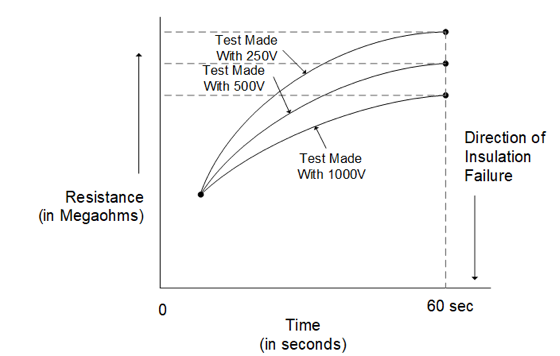
The Step-Voltage test uses different test voltage levels over fixed durations and results are compared. Good insulation will withstand an increase in voltage stress with relatively constant resistance measurements. Poor insulation, however, will show lower IR readings as voltages increase.
Increasing the voltage stress on the cable can provide more detailed information than the single Spot Test as, for example, the effects of a growing water tree may not be apparent in the readings until higher voltages are applied.
As an alternative to step changes in voltage, a Ramp Test may be used with voltage increasing at a steady state. This offers even more data about anomalies in the system.
The periods between IR tests should be such that there is enough data to determine the rate of IR loss so that better strategic decisions can be made for planning and maintenance activities. Ultimately, correctly monitoring and trending IR data has the potential to save millions of dollars in disruptive interventions.
To monitor insulation faults, Megohmmeter testing of IR has traditionally been carried out at regular intervals; typically every 12 or even 6 months. In more recent times, Line Insulation Monitor (LIM) devices have been installed to provide continuous monitoring.
The data from continuous monitoring is important as detection of areas at risk of fault is based on seeing trends in the data and a clearer picture can be provided with measurements every minute rather than months apart.
Alarms can be set to trigger if the IR value falls below a pre-defined level, or the rate of change in a decreasing IR similarly falls below a given value.
LIM devices typically superimpose low voltage signals onto the power conductors. With reference to system ground, the LIM searches for leakage currents caused by insulation faults. Higher test voltages used in offline IR testing, such as those used by Megohmmeter units, will provide greater measurement accuracy as leakage currents are higher – but this comes at a higher cost as specialised personnel need to be deployed to carry out these tests, which can take up to an entire day to complete. LIM device accuracy is typically <15% whereas Megohmmeters typically offer accuracies between ±2 to 5%.
Once a LIM records an alarm, therefore, an IR test is then generally scheduled for more accurate measurements to be taken prior to action.
Problems arise if alarms are silenced or LIM devices bypassed as the risk to human life may not have been realised.
The alarm and trip levels also have to be properly defined for safety reasons. Why, for example, has the market settled on an IR generic alarm value of 100kΩ when it should be a calculated value specific to the system? Following an IR test, the operator is still presented with a challenge.
The IR alone does not tell the operator which component is at fault and resolution of an issue often requires a costly and time-consuming diagnostic campaign. However, modern technology offers operators a solution to this challenge.
LIM devices are now available that can be installed subsea to form a distributed LIM network that communicates back to a topside monitoring device. These units measure the IR of the entire system but critically they can also measure the IR upstream and downstream of their location.
By placing these in strategic locations in the subsea network, a complete subsea distribution system electrical integrity map is created; giving operators not only information about the general insulation integrity beneath the water but also the information required to reduce the cost of maintenance and repairs. Indeed, having the visibility of which leg of the subsea system is failing offers a huge financial gain.
Reducing the pain of low IR readings
Fundamentally, a low IR reading presents an operator with a dilemma for which they need to balance risk and reward. Many factors come into this decision, including the age of the field and estimates of when low IR will result in failures.
The safety of human life is of paramount importance and, while the IT earth system is tolerant of a single fault, processes need to be in place to repair in a timely manner as even a fault that is 30km away from the platform is dangerous to human life at the point where the umbilical enters the termination panel on the topside.
One of the biggest challenges is to balance risk with the huge costs of subsea interventions to repair failing insulation. Using a distributed LIM system offers significant reward in terms of the time and cost of such an intervention, but any subsea work is still costly and impacts productivity. There is, however, solution that has been proven to improve IR without the need for subsea intervention.
The V-LIFE system from Viper Innovations is a LIM device with a difference. As well as continuously monitoring IR levels, this breakthrough technology uses an electro-kinetic and electromechanical process to actively heal and improve cable insulation. It can be used as a preventative measure or to extend the life of a failing electrical distribution system.
Whether used for rejuvenation, reduced risk, a way of better controlling maintenance schedules, or to postpone field abandonment for a platform where repair is not economically viable; this technology revolutionises the way we can think about handling the challenges of insulation deterioration.
Summary
Insulation resistance needs to be maintained at safe levels to shield against failures and to protect human life. For subsea cables, the traditional cost of maintenance and repair is extremely high. Continuous monitoring helps to provide a clearer picture about trends in IR so operators can make better strategic decisions.
Advances in technology also offer alternatives that complement traditional Megohmmeter IR tests. Distributed LIM networks give a way to see what is happening in particular parts of the subsea network, making the challenges of repair much less time-consuming and costly.
Knowing where a fault lies, also reduces the number of disconnects required during the fault-finding process and so reduces the risk of introducing additional faults or weaknesses in the system.
Being able to heal as well as monitor IR without intervention is a huge leap forward. Healing technology has been installed on over 50 offshore systems for twenty different operators and the subsequent increased IR readings verified through traditional Megohmmeter testing processes.
Once this technology was considered to be ‘smoke and mirrors’, but now it is proven with a successful installed base. V-LIFE has changed the landscape for subsea maintenance.
